EFFECTIVE: February 2, 2004 Owner's Manual SUPPLEMENT ELECTRIC CHAIN HOIST ER and NER SERIES 8 Ton through 20 Ton Capacity 4.7 HP MOTOR VERSION Code, Lot and Serial Number WARNING This equipment should not be installed, operated or maintained by any person who has not read and understood all the contents of this manual. Failure to read and comply with the contents of this manual can result in serious bodily injury or death, and/or property damage.
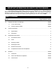
IMPORTANT INFORMATION ON HOW TO USE THIS MANUAL This OWNER’S MANUAL SUPPLEMENT is intended for use in combination with the “Owner’s Manual for Electric Chain Hoist ER and NER Series 1/8 through 5 Ton Capacity”. Refer to the Table of Contents below to determine the location(s) of information pertaining to your hoist. References to the “Owner’s Manual for Electric Chain Hoist ER and NER Series 1/8 through 5 Ton Capacity” will be designated by the use of the acronym “EROM”. Table of Contents Section 1.0 2.
Section 5.0 6.0 Page Number/Location Inspection……………………………….………………………………….…………..…….. 13 and EROM 5.1 General EROM 5.2 Inspection Classification EROM 5.3 Frequent Inspection EROM 5.4 Periodic Inspection EROM 5.5 Occasionally Used Hoists EROM 5.6 Inspection Records EROM 5.7 Inspection Methods and Criteria 13 and EROM Maintenance & Handling……………………………………………………….……………. 16 and EROM 6.1 Count/Hour Meter EROM 6.2 Lubrication 16 and EROM 6.3 Motor Brake 16 and EROM 6.
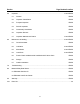
2.0 Technical Information 2.1 Specifications 2.1.1 Product Code 2.1.2 8 through 20 ton hoists are available in one standard specification: • Dual Speed Motor • Mechanical Load Brake/Friction Clutch Combination • Count/Hour Meter • Upper/Lower Limit Switch 2.1.
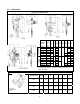
2.2 Dimensions Table 2-2 Hoist Dimensions ER080S Product Code Headroom: C ER080S ~ ER100L L* a b d e g h i (ft) (in) (in) (in) (in) (in) (in) (in) 42.0 8.7 30.9 23.8 15.5 15.5 2.4 11.3 7.5 52.6 9.2 DUAL SPEED SINGLE SPEED (in) 39.4 14.0 20.4 8.9 ER100L-LG 39.7 8.7 28.0 ER100S 52.6 9.2 34.2 ER150S 60.6 10.5 41.3 3.1 ER200S 65.0 49.1 3.4 2.4 11.3 7.5 ER080SD ~ 42.0 8.7 ER100LD 52.6 9.2 32.2 23.8 15.5 16.8 39.4 14.0 20.
3.0 Preoperational Procedures 3.1 Fill Gear Box with Oil CAUTION 3.1.1 DO NOT use any oil or quantity other than that listed below. 3.1.2 For a new hoist the correct quantity and type of oil is supplied with the hoist in separate containers. Remove the fill plug from the top of the hoist and connect the flexible pour tube to the oil container. Pour in all of the oil from the separate containers, then replace the fill plug. 3.1.3 Refer to Section 6.
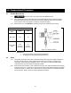
Figure 3-2 Chain Component Arrangement Table 3-2 Chain Stopper Placement 3.2.3 3.2.4 Capacity Code Without Chain Container 080S, 100L, 100S, 150S, 200S 9 link from the free end th With Chain Container rd 3 link from the free end When the optional canvas chain container(s) is used, unfold it fully and install it on the hoist body(ies) as shown in Figure 3-3.
Figure 3-3 Installation of Chain Container 3.2.5 3.2.6 3.2.7 When using an optional steel chain container, refer to the instructions and/or assembly drawing(s) provided with the container for correct assembly and attachment. WARNING Verify that the load chain is not twisted or tangled prior to operating the hoist. Make sure the bottom hook is not capsized. See Figures 3-4. Correct all chain irregularities before conducting the first hoist operation.
3.3.2 3.4 See Section 6.7 of the EROM for outdoor installation considerations. Mounting the Hoist 3.4.1 Manual Trolley - Follow instructions in Owner’s Manual provided with the trolley. 3.4.2 Motorized Trolley - Follow instructions in Owner’s Manual provided with the trolley. 3.4.3 Hook Mounted to a Fixed Location - Attach the hoist’s top hook to the fixed suspension point. 3.4.
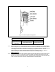
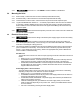
Figure 3-5 Pendant and Power Supply Cable Connections for ER080S and ER100L Figure 3-6 Pendant and Power Supply Cable Connections for ER100S, ER150S and ER200S 10
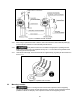
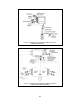
Figure 3-7 Power Supply Cable Festooning and Guide Wire Location Power Supply Cable - Installation If the hoist is hook mounted to a fixed support ensure that the Power Supply Cable is properly installed and supported between the hoist and the electrical power supply. If the hoist is installed on a manual trolley, then the Power Supply Cable must be installed along the beam that the trolley runs on. For curved beams a special cable suspension system will be needed, and this instruction does not apply.
3.6 Preoperational Checks and Trial Operation 3.6.1 3.6.2 Refer to the hoist’s nameplate and record the hoist's Code, Lot and Serial Number in the space provided on the cover of this manual. WARNING Confirm the adequacy of the rated capacity for all slings, chains, wire ropes and all other lifting attachments before use. Inspect all load suspension members for damage prior to use and replace or repair all damaged parts. WARNING 3.6.
5.0 Inspection NOTICE The information listed in this section is intended to supplement Section 5.7 of the EROM. Table 5-3 Hoist Inspection Methods and Criteria Use this table in conjunction with Table 5-3 of the EROM. The entries in this table replace in their entirety the corresponding entries in Table 5-3 of the EROM. Item Method Criteria Action Hooks - Fretting wear Measure The "u" and "t" dimensions should not be less than discard value listed in Table 5-4 Replace.
Table 5-3 Hoist Inspection Methods and Criteria Use this table in conjunction with Table 5-3 of the EROM. The entries in this table replace in their entirety the corresponding entries in Table 5-3 of the EROM. Item Method Motor Brake Measure, Visual Criteria Action Motor brake gap should be adjusted to the distance shown in Table 6-3 before measuring the brake wear. Brake lining dimension “A” should not be less than discard value listed in Table 5-6. Refer to Section 6.
Table 5-5 Chain Wear Dimensions “P” Dimension inch (mm) Capacity Code 080S, 100L, 100S, 150S, 200S “d” Dimension inch (mm) Standard Discard Standard Discard 6.75 (171.5) 6.85 (174.1) 0.44 (11.2) 0.40 (10.1) Table 5-6 Motor Brake Wear Dimensions NOTICE Brake must be properly adjusted before measuring "A". See Section 6.3 of EROM "A" Dimension - inch (mm) Capacity Code 080S, 100L, 100S, 150S, 200S Single Speed Dual Speed Standard Discard Standard Discard 0.83 (21) 0.77 (19.5) 1.
6.0 Maintenance and Handling 6.2 Lubrication 6.2.1 Load Chain § 6.2.2 Hooks and Suspension Components: § 6.2.3 Refer to 6.2.1 of the EROM. Refer to 6.2.2 of the EROM. Gear Box: § Refer to 6.2.3 of the EROM except use the following table for checking oil level. Table 6-3 Criteria for Checking Hoist Gear Oil Level Capacity Code 080S, 100L, 100S, 0150S, 200S 6.3 Oil Level (Hoist at level position) Min Max 1“ below bottom edge of check hole Even with bottom edge of check hole.
1) 2) 3) CAUTION The hoist must be properly powered and operational in order to perform the following procedures. WARNING Be certain that the replacement chain is obtained from Harrington and is the exact size, grade and construction as the original chain. The new load chain must have an odd number of links so that both its end links have the same orientation. If the load chain is being replaced due to damage or wear out, destroy the old chain to prevent its reuse.
Figure 6-3 Chain Replacement for 080S and 100L 6.4.3 1) 2) 3) Load Chain Replacement for ER100S, ER150S and ER200S: CAUTION The hoist must be properly powered and operational in order to perform the following procedures. WARNING Be certain that the replacement chain is obtained from Harrington and is the exact size, grade and construction as the original chain. The new load chain must have an odd number of links so that both its end links have the same orientation.
11) Remove the remaining Stopper and Chain Spring from the old chain. Inspect and replace any damaged or worn parts. Install the Stopper and Chain Spring to the end of the new chain. Refer to Section 3.2 in this supplement for correct location. 12) For hoists without a chain container, attach the ends of the chain to Chain Guide A on each body with the socket bolt, and lock nut (see Figure 3-2). Ensure that all chain parts remain free of twists and correct any if found.
10.0 8 to 20 Ton Parts List When ordering Parts, please provide the Hoist code number, lot number and serial number located on the Hoist nameplate (see fig. below). Reminder: Per sections 1.1 and 3.5.1 to aid in ordering Parts and Product Support, record the Hoist code number, lot number and serial number in the space provided on the cover of this manual. ER Series Nameplate The parts list is arranged into the following sections: Section Parts Common to Plate Suspension (lug mount) and Hook Mount.
This Page Intentionally Left Blank 21
10.
10.1 Housing and Motor Parts Single Body Hoist Figure No.
10.1 Housing and Motor Parts Single Body Hoist Figure No.
This Page Intentionally Left Blank 25
10.
10.2 Gearing Parts Single Body Hoist Figure No.
10.3 Chaining Parts Figure 10-3 Chaining Parts Figure Part Name No.
This Page Intentionally Left Blank 29
10.
10.4 Bottom Hook Parts 8 & 10 Ton Figure No.
10.
10.5 Bottom Hook Parts 15 & 20 Ton Figure No.
10.
10.6 Electric Parts Figure Part Name No.
10.
10.7 Push Button Control Station Parts Figure Part Name No.
10.8 Chain Container Parts 8 & 10(L) Ton Figure 10-8 Chain Container Parts 8 & 10(L) Ton Figure Part Name No.
10.9 Chain Container Parts 10(S) thru 20 Ton Figure 10-9 Chain Container Parts 10(S) & 20 Ton Figure Part Name No.
10.
10.10 Push or Geared Type Control Station and Cable Parts Figure No.
10.10 Push or Geared Type Control Station and Cable Parts Figure No.
This Page Intentionally Left Blank 43
10.
10.11 Top Suspension Plate parts 8 & 10 Ton ER1HS1003 Parts Per Hoist 1 2 Top Suspension Plate B Assembly 1 ER1HS5004 1 ER1IS5004 3 Guide Roller 4 E6S062075 4 E6S062075 4 Top Stay Bolt 3 E6S007075 4 E6S007075 6 Top Idle Sheave Assembly 1 ER1HS1051 1 ER1HS1051 7 Top Suspension Plate A Assembly 1 ER1HS5003 1 ER1IS5003 8 Spring Washer 6 E6S082075 8 E6S082075 Figure Part Name No.
10.
10.12 Top Suspension Plate Parts 15 & 20 Ton ER1JS1003 Parts Per Hoist 1 2 Top Suspension Plate B 1 ER1JS5004 1 ER1KS5004 3 Top Stay Bolt 6 E6S007075 7 E6S007075 4 Guide Roller 6 E6S062075 8 E6S062075 5 Top Idle Sheave Assembly 2 ER1HS1051 3 ER1HS1051 7 Top Suspension Plate A 1 ER1JS5003 1 ER1KS5003 8 Spring Washer 12 E6S082075 14 E6S082075 Figure No.
10.
10.13 Hook Type Control Station and Cable Parts Figure No.
10.
10.
10.
10.14 Top Hook Parts Figure Part Name No.
www.harringtonhoists.com Harrington Hoists, Inc. 401 West End Avenue Manheim, PA 17545 Phone: 717-665-2000 Toll Free: 800-233-3010 Fax: 717-665-2861 Harrington Hoists – Western Division 2341 Pomona Rincon Rd. #103 Corona, CA 92880-6973 Phone: 909-279-7100 Toll Free: 800-317-7111 Fax: 909-279-7500 ERLC4.