EFFECTIVE: October 6, 2010 ELECTRIC CHAIN HOIST ED SERIES 125 through 525 Lb. Capacity Code, Lot and Serial Number This equipment should not be installed, operated or maintained by any person who has not read and understood all the contents of this manual. Failure to read and comply with the contents of this manual can result in serious bodily injury or death, and/or property damage.
Table of Contents Section 1.0 2.0 3.0 4.0 Page Number Important Information and Warnings ……………………………………………………………………… 4 1.1 Terms and Summary 1.2 Warning Tags and Labels Technical Information…………………………………………………………………………….…………. 8 2.1 Specifications 2.2 Dimensions 2.3 Part Names Pre-operational Procedures ……………………………………………………………………………… 13 3.1 Fill Gear Box with Oil 3.2 Chain 3.3 Load Chain Lubrication 3.4 Chain Container 3.5 Mounting Location 3.6 Mounting the Hoist 3.
Section 5.0 6.0 Page Number Inspection ………………………………………………………………………………………………….. 25 5.1 General 5.2 Inspection Classification 5.3 Frequent Inspection 5.4 Periodic Inspection 5.5 Occasionally Used Hoists 5.6 Inspection Records 5.7 Inspection Methods and Criteria Maintenance & Handling …………………………………………………………………………………. 32 6.1 Lubrication 6.2 Load Chain 6.3 Mechanical Load Brake with Friction Clutch 6.4 Fuses 6.5 Storage 6.6 Outdoor Installation 7.
1.0 Important Information and Warnings 1.1 Terms and Summary This manual provides important information for personnel involved with the installation, operation and maintenance of this product. Although you may be familiar with this or similar equipment, it is strongly recommended that you read this manual before installing, operating or maintaining the product. Danger, Warning, Caution and Notice Throughout this manual there are steps and procedures that can present hazardous situations.
Equipment described herein is not designed for and MUST NOT be used for lifting, supporting, or transporting people, or for lifting or supporting loads over people. Equipment described herein should not be used in conjunction with other equipment unless necessary and/or required safety devices applicable to the system, crane, or application are installed by the system designer, system manufacturer, crane manufacturer, installer, or user.
HAZARDOUS VOLTAGES ARE PRESENT IN THE CONTROL BOX, OTHER ELECTRICAL COMPONENTS, AND CONNECTIONS BETWEEN THESE COMPONENTS. Before performing ANY mechanical or electrical maintenance on the equipment, de-energize (disconnect) the main switch supplying power to the equipment; and lock and tag the main switch in the de-energized position. Refer to ANSI Z244.1, “Personnel Protection – Lockout/Tagout of Energy Sources”. Only trained and competent personnel should inspect and repair this equipment.
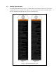
1.2 Warning Tags and Labels The warning tag illustrated below in Figure 1-1 is supplied with each hoist shipped from the factory. If the tag is not attached to your hoist’s pendant cord or cylinder control, order a tag from your dealer and install it. Read and obey all warnings attached to this hoist. Tag is not shown actual size.
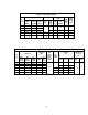
2.0 Technical Information 2.1 Specifications 2.1.1 Product Code 2.1.
Table 2-1 Hoist Motor Rating Cap. Single Speed S Model Dual Speed DS Model Dual Adjustable DA Model 125 ED125S ED125DS ED125DA 220 ED220S ED220DS ED220DA 250 ED250S ED250DS ED250DA 350 ED350S ED350DS ED350DA 0.8 400 ED400S ED400DS ED400DA 525 ED525S ED525DS ED525DA (lbs.) Intermittent Duty Rating Motor Product Code Output (Hp) 0.4 Rated Current at 115V (Amps) Duty Rating % ED Max. Start Freq.
2.2 Dimensions Table 2-3 Hoist Dimensions Cap. (lbs) Headroom C (in) S & DS Model Standard Lift L (ft) DA Model S & DS Model DA Model Push Button Cord L (ft) S & DS Model S & DS Model a (in) d (in) e (in) f (in) 14.6 7.4 7.2 8.1 16.9 8.1 8.8 8.6 g (in) h (in) i (in) 4.9 3.1 5.3 3.3 j (in) k (in) EDII EDIII EDII EDIII 11.8 12.4 36.6 37.2 350 12.8 13.0 37.6 37.8 400 11.8 12.4 36.6 37.2 14.6 7.4 7.2 8.1 4.9 3.1 13.4 525 12.8 13.0 37.6 37.8 16.9 8.
Table 2-4 Mini Trolley Dimensions Maximum Capacity (lbs.) Product Code Adjustable Beam Width B (in) Min. Radius for Curve (in) Net Weight (lbs.) Approx. Shpg. Weight (lbs.) 525 ET525 1.97 – 3.94 23.6 4.0 5.0 Table 2-5 Mini Trolley Headroom Headroom C (in.) Cap. (lbs.) ED II ED III S & DS Model DA Model S & DS Model DA Model 9.9 34.5 10.5 35.3 10.9 35.7 11.1 35.9 400 9.9 34.5 10.5 35.3 525 10.9 35.7 11.1 35.
2.
3.0 Pre-operational Procedures 3.1 Fill Gear Box with Oil 3.1.1 Use only Harrington ED brand oil. The oil is specially blended and should be purchased from Harrington. Refer to parts list for part number. 3.1.2 For a new hoist the correct quantity and type of oil is pre-supplied in the gearbox. 3.1.3 Refer to Section 6.1 when replacing the gear oil or checking the gear oil level. Table 3-1 Amount of Gear Oil Capacity Code quarts liters 0.28 0.27 0.37 0.
Figure 3-2 Chain Component Arrangement for Hoists with Upper Limit Switch Only 3.3 Load Chain Lubrication 3.3.1 3.3.2 Always lubricate load chain weekly, or more frequently, depending on severity of service. Always make sure to apply ISO VG 46 or 48 or equivalent machine oil. Insufficient oil lubrication will accelerate Load Chain wear.
3.4 Chain Container 3.4.1 Follow the instructions below to install the Chain Container. Refer to Figure 3-3. 1) Feed the Load Chain into the Chain Container beginning with the no-load end. Take care to avoid twisting or tangling the Load Chain. 2) Attach the Chain Container to the Chain Guide (1) with the Socket Bolt (2) and the U-Nut (3). 3) Attach the Split Pin (4) to prevent the U-Nut (3) from backing off. o 4) Bend the Split Pin ends 90 or more.
3.7.3 This instruction applies to installations where the hoist is installed hook mounted to a fixed suspension point or installed on a manual trolley. In this case the hoist is controlled by a pendant with two push buttons – one for raising and one for lowering. Pendant Cord The Pendant Cord is hard wired to the hoist. Make this connection as follows: 1.) Single and Dual Speed Models (S & DS) Refer to Figure 3-4. The Push Button Cord is factory installed onto the hoist body.
Power Supply Cable - Installation If the hoist is hook mounted to a fixed support ensure that the Power Supply Cable is properly installed and supported between the hoist and the electrical power supply. If the host is installed on a manual trolley, then the Power Supply Cable must be installed along the beam that the trolley runs on. For curved beams a special cable suspension system will be needed, and this instruction does not apply.
3) Refer to Figure 3-6 and assemble the Trolley Frames, Adjusting Spacers and Socket Bolts onto the Top Yoke. Install and hand tighten the Hex Nuts on the Socket Bolts. Verify that dimension “A” is approximately 0.12 - 0.16 in (3-4mm) greater than “B” (flange width).
3.9 Pre-operational Checks and Trial Operation 3.9.1 Confirm the adequacy of the rated capacity for all slings, chains, wire ropes and all other lifting attachments before use. Inspect all load suspension members for damage prior to use and replace or repair all damaged parts. 3.9.2 Verify and correct all chain irregularities prior to operating the hoist. For reference see Section 3.2. 3.9.3 Measure and record the “k” dimension of all hooks on hoist.
4.0 Operation 4.1 Introduction DO NOT WALK UNDER A SUSPENDED LOAD HOIST OPERATORS SHALL BE REQUIRED TO READ THE OPERATION SECTION OF THIS MANUAL, THE WARNINGS CONTAINED IN THIS MANUAL, INSTRUCTION AND WARNING LABELS ON THE HOIST OR LIFTING SYSTEM, AND THE OPERATION SECTIONS OF ANSI/ASME B30.16 and ANSI/ASME B30.10. THE OPERATOR SHALL ALSO BE REQUIRED TO BE FAMILIAR WITH THE HOIST AND HOIST CONTROLS BEFORE BEING AUTHORIZED TO OPERATE THE HOIST OR LIFTING SYSTEM.
4.2 Shall’s and Shall Not’s for Operation Improper operation of a hoist can create a potentially hazardous situation which, if not avoided, could result in death or serious injury, and substantial property damage. To avoid such a potentially hazardous situation THE OPERATOR SHALL: • NOT lift more than rated load for the hoist. • NOT operate unless load is centered under hoist. • NOT use damaged hoist or hoist that is not working properly.
Improper operation of a hoist can create a potentially hazardous situation which, if not avoided, could result in minor or moderate injury, or property damage. To avoid such a potentially hazardous situation THE OPERATOR SHALL: • Maintain a firm footing or be otherwise secured when operating the hoist. • Use the hoist manufacturer’s recommended parts when repairing the unit. • Check brake function by tensioning the hoist prior to each lift operation.
4.3.4 Dual Speed Pendant Model (DS) Low Speed Adjustment – The Pendant has a low speed adjustment which allow the low speed to be adjusted to suit the application or compensate for low or high supply voltage. Adjust the low speed as follows: 1) Before proceeding, ensure that the electrical supply for the hoist or trolley has been de-energized (disconnected). Lock out and tag out in accordance with ANSI Z244.1 “Personnel Protection -Lockout/Tagout of Energy Sources”.
4.3.6 Dual Speed Cylinder Control (DA) Model (DS) Low and High Speed Adjustment – The controller has speed adjustments which allow the lifting and lowering speeds to be adjusted to suit the application or compensate for low or high supply voltage. Turn the Low Speed Adjustment Switch (right side of operating box) or High Speed Adjustment Switch (left side of operating box, model ED3 only) with screw driver or the knob provide to adjust the speed.
5.0 Inspection 5.1 General 5.1.1 5.2 The inspection procedure herein is based on ANSI/ASME B30.16. The following definitions are from ANSI/ASME B30.16 and pertain to the inspection procedure below. Designated Person – a person selected or assigned as being competent to perform the specific duties to which he/she is assigned.
5.3 Frequent Inspection 5.3.1 Inspections should be made on a FREQUENT basis in accordance with Table 5-1, “Frequent Inspection.” Included in these FREQUENT Inspections are observations made during operation for any defects or damage that might appear between Periodic Inspections. Evaluation and resolution of the results of FREQUENT Inspections shall be made by a designated person such that the hoist is maintained in safe working condition.
5.5 Occasionally Used Hoists 5.5.1 5.6 5.7 Hoists that are used infrequently shall be inspected as follows prior to placing in service: Hoist Idle More Than 1 Month, Less Than 1 Year: Inspect per FREQUENT Inspection criteria in Section 5.3. Hoist Idle More Than 1 Year: Inspect per PERIODIC Inspection criteria in Section 5.4. Inspection Records 5.6.
Table 5-3 Hoist Inspection Methods and Criteria Item Method Criteria Action Visual, Function Bearing parts and surfaces should not show significant wear, and should be free of dirt, grime and deformations. Hook should rotate freely with no roughness. Clean/lubricate, or replace as required. Hooks - Hook Latches Visual, Function Latch should not be deformed. Attachment of latch to hook should not be loose. Latch spring should not be missing and should not be weak.
Table 5-3 Hoist Inspection Methods and Criteria Item Method Criteria Action Cushion Rubber Visual Should be free of significant deformation. Replace. Pendant - Switches Function Depressing and releasing push buttons should make and break contacts in switch contact block and result in corresponding electrical continuity or open circuit. Push buttons should be interlocked either mechanically or electrically to prevent simultaneous energization of circuits for opposing motions (e.g. up and down).
Table 5-5 Top Hook & Bottom Hook Dimensions “k” Measured When New: Top: _________________________ Bottom: ______________________ Capacity (lbs) Hook *Nominal "k" Dimension inch (mm) "u" Dimension inch (mm) "t" Dimension inch (mm) Standard Discard Standard Discard Bottom 1.73(44). 0.67(17) 0.60(15.3) 0.48(12.1) 0.43(10.9) Top 1.77(45) 0.67(17) 0.60(15.3) 0.28(7.0) 0.25(6.3) 125 to 525 * These values are nominal since the dimension is not controlled to a tolerance.
Table 5-7 Mini Trolley Inspection Methods and Criteria Item Method Criteria Action Visual, Auditory Mechanisms should be properly adjusted and should not produce unusual sounds when operated. Repair or replace as required. Mechanical Components Visual, Auditory, Vibration, Function Trolley components including, suspension shafts, track wheels, track wheel axles, suspension bolts, shafts, bearings and pins should be free of cracks, distortion, significant wear and corrosion.
6.0 Maintenance and Handling 6.1 Lubrication 6.1.1 6.1.2 6.1.3 Load Chain For longer life, lightly coat the Load Chain with machine or gear oil. Ensure that the oil is applied to the bearing surfaces of the Load Chain links. The chain should be lubricated every 3 months (more frequently for heavier usage or severe conditions). Lubricate Load Chain with grade ISO VG 46 or 48 oil or equivalent machine/gear oil. For dusty environments, it is acceptable to substitute a dry lubricant.
4) Remove all chain components including the Bottom Hook Set Assembly, Stoppers, Cushion Rubbers, Washers and Chain Pin from the chain for reuse on new chain. Inspect and replace any damaged or worn parts. 5) Using a C-link, attach the new chain to the end link of the old chain on the no-load side. The end link of the new Load Chain should be connected so that the welded portions of the Load Chain's standing links are oriented to the outside as they pass over the sheave. Refer to Figure 6-1.
6.4 Fuses 6.4.1 Spare fuses are attached inside the controller cover (the capacity/nameplate side). The fuse sizes are shown in the Table 6-1. Table 6-1 Fuse Size Capacity Main Fuse Rating (lbs) (Amps) 125 10 220 250 6.4.2 6.5 15 400 10 525 15 In addition, current model DS and DA units have a second smaller fuse (5 x 20mm) rated at 0.1 AMPS. Storage 6.5.1 6.6 350 The storage location should be clean and dry. Outdoor Installation 6.6.
7.0 Troubleshooting HAZARDOUS VOLTAGES ARE PRESENT IN THE HOIST AND IN CONNECTIONS BETWEEN COMPONENTS. Before performing ANY troubleshooting on the equipment, de-energize the supply of electricity to the equipment, and lock and tag the supply device in the de-energized position. Refer to ANSI Z244.1, “Personnel Protection Lockout/Tagout of Energy Sources.” Only Trained and competent personnel should inspect and repair this equipment.
Table 7-1 Troubleshooting Guide Symptom Hoist lowers but will not lift Hoist will not lift rated load or does not have the proper lifting speed Load drifts excessively when hoist is stopped Cause Remedy Hoist overloaded Reduce load to within rated capacity of hoist. Low voltage in hoist's power supply Determine cause of low voltage and bring to within plus or minus 10% of the voltage specified on the motor nameplate. The voltage should be measure at the hoist contactor.
Table 7-1 Troubleshooting Guide Symptom Hoist operates intermittently DA Model - Hook drops out of cylinder chuck Actuation of Limit Switch does not stop hoist Cause Remedy Collectors making poor contact Check movement of spring loaded arm, weak spring, connections, and shoe. Replace as needed. Contactor contacts arcing Check for burned contacts. Replace as needed. Loose connection in circuit Check all wires and terminals for bad connections. Replace as needed.
8.0 Warranty All products sold by Harrington Hoists, Inc.
9.0 Parts List When ordering Parts, please provide the Hoist code number, lot number and serial number located on the Hoist nameplate (see fig. below). Reminder: Per sections 1.1 and 3.9.4 to aid in ordering Parts and Product Support, record the Hoist code number, lot number and serial number in the space provided on the cover of this manual. ED Nameplate The parts list is arranged into the following sections: Section Page 9.1 Housing, Motor, and Gearing Parts……………………………………………………………………...40 9.
9.
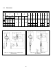
9.1 Fig. No. 1 2 3 4 Part Name Parts Per Hoist Housing, Motor, and Gear Parts Capacity (lbs.) 125 220 250 400 Top Hook Assembly 1 E2D1001125 Hook Latch Assembly 1 L41071008 Top Yoke Complete Set 1 E2D1011125 350 525 E2D1011350 Top Pin Assembly 2 M3041010 Bottom Hook Comp. Set 1 E2D1021125 Latch Assembly.
9.1 Housing, Motor, and Gear Parts Fig. No. 33 Part Name Parts Per Hoist Motor Complete Set for 120V, 50/60 Hz 1 34 Armature Assembly for 120V, 50/60 Hz 35 Stator Assembly 36 Capacity (lbs.
This Page Intentionally Left Blank 43
9.
9.2 Fig. No. 1 Part Name Parts Per Hoist Power Supply and Pendant Parts Capacity (lbs.
9.2 Power Supply and Pendant Parts Fig. No. Part Name Parts Per Hoist Capacity (lbs.
This Page Intentionally Left Blank 47
9.
9.3 Fig. No. 1 Part Name Parts Per Hoist Electric Parts Capacity (lbs.
9.4 Mini Trolley Parts FIGURE 9-4 MINI TROLLEY PARTS 9.4 Mini Trolley Parts Fig. No. Part Name Parts Per Hoist Capacity (525lbs.
Notes 51
www.harringtonhoists.com Harrington Hoists, Inc. 401 West End Avenue Manheim, PA 17545-1703 Phone: 717-665-2000 Toll Free: 800-233-3010 Fax: 717-665-2861 Harrington Hoists – Western Division 2341 Pomona Rd.