EFFECTIVE: September 13, 2012 MANUAL CHAIN HOIST CF SERIES MODEL CF4 1/2 Ton through 5 Ton Capacity Code, Lot and Serial Number This equipment should not be installed, operated or maintained by any person who has not read and understood all the contents of this manual. Failure to read and comply with the contents of this manual can result in serious bodily injury or death, and/or property damage.
Table of Contents Section 1.0 2.0 3.0 4.0 5.0 Page Number Important Information and Warnings ……………………………………………………………………… 4 1.1 Terms and Summary 1.2 Warning Tags and Labels Technical Information…………………………………………………………………………….…………. 7 2.1 Specifications 2.2 Dimensions 2.3 Optional Equipment Preoperational Procedures ……………………………………………………………………………… 11 3.1 Chain 3.2 Attachment Points 3.3 Mounting the Hoist 3.
Section 5.7 6.0 Page Number Inspection Methods and Criteria Maintenance & Handling …………………………………………………………………………………. 25 6.1 Lubrication 6.2 Disassembly, Assembly and Adjustment 6.3 Hoist Disassembly 6.4 Hoist Assembly 6.5 Storage 6.6 Outdoor Installation 7.0 Troubleshooting …………………………………………………………………………………………… 33 8.0 Warranty …………………………………………………………………………………………………… 36 9.
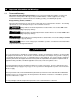
1.0 Important Information and Warnings 1.1 Terms and Summary This manual provides important information for personnel involved with the installation, operation and maintenance of this product. Although you may be familiar with this or similar equipment, it is strongly recommended that you read this manual before installing, operating, or maintaining the product. Danger, Warning, Caution, and Notice Throughout this manual there are steps and procedures that can present hazardous situations.
Equipment described herein is not designed for and MUST NOT be used for lifting, supporting, or transporting people, or for lifting or supporting loads over people. Equipment described herein should not be used in conjunction with other equipment unless necessary and/or required safety devices applicable to the system, crane, or application are installed by the system designer, system manufacturer, crane manufacturer, installer, or user.
1.2 Warning Tags and Labels The warning tag illustrated below in Figure 1-1 is supplied with each hoist shipped from the factory. If the tag is not attached to your hoist’s no-load side of the load chain, order a tag from your dealer and install it. Read and obey all warnings attached to this hoist. Tag is not shown actual size.
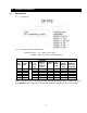
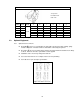
2.0 Technical Information 2.1 Specifications 2.1.1 Product Code 2.1.2 Operating Conditions and Environment Temperature range: Humidity: -4° to +140°F (-20° to +60°C) 100% or less (Not an Underwater Device) Table 2-1 Hoist Specifications Std. Cap. Product Lift (Tons) Code (ft) ½ 1 1½ 2 3 5 CF005 CF010 CF015 CF020 CF030 CF050 10 Pull to Lift Load (lbs) 60 72 84 80 92 92 Load Chain Net Overhaul Diameter Ratio (mm) x Weight Chain Fall (lbs) Lines 5.0 x 1 6.3 x 1 7.1 x 1 6.3 x 2 7.1 x 2 7.
2.2 Dimensions Cap. (Tons) Product Code 1/2 1 1 1/2 2 3 5 CF005 CF010 CF015 CF020 CF030 CF050 CF005 to CF015 Figure 2-1 Table 2-2 Hoist Dimensions Headroom a b d c (in) (in) (ft) (in) 12.8 14.6 17.3 20.1 23.2 24.4 5.4 5.8 6.0 5.8 6.0 6.0 5.9 6.9 8.0 8.0 9.4 13.5 CF020 to CF030 Figure 2-2 8 10 10 10 10 10 10 e (in) f (in) g (in) 2.0 2.3 2.4 2.3 2.4 2.4 2.4 2.9 3.4 2.3 2.7 4.5 1.1 1.1 1.3 1.4 1.7 1.
Table 2-3 Hook Dimension* T = Top Hook B = Bottom Hook Units = inch Cap. (Tons) 1/2 Product Code CF005 Hook a b c d e g 0.8 0.5 0.7 0.5 1.4 1.1 1 CF010 1.0 0.6 0.9 0.6 1.7 1.1 1½ CF015 1.2 0.8 1.0 0.8 1.9 1.3 2 CF020 1.4 0.9 1.2 0.9 2.0 1.4 3 CF030 1.8 1.1 1.5 1.1 2.2 1.7 5 CF050 2.2 1.4 1.9 1.4 2.5 1.8 T&B *Refer to Section 5.7 for inspection dimensions and limits. 2.3 Optional Equipment 2.3.
2.3.2 Optional Inspection Hooks The Inspection Hook is designed to facilitate the inspection of the internal surfaces of the hook yoke and shank portion of the hook itself. The Inspection Hook is suitable for applications where inspection of the internal parts of the hook set is required. The inspection hook uses the standard Harrington hook set and is assembled with high-strength locking fasteners instead of rivets. Inspection hooks are available in top and bottom versions. Refer to Figure 2-5.
3.0 Preoperational Procedures 3.1 Chain 3.1.1 Verify that the load chain is not twisted or tangled prior to operating the hoist. Make sure the bottom hook on the 2 (CF020) through the 5 (CF050) Ton multiple fall hoists is not capsized. See Figures 3-1 and 3-2. Correct all chain irregularities before conducting the first hoist operation.
3.2 Attachment Points 3.2.1 Prior to attaching the hoist ensure that all attachment points, suspension components and supporting structure are adequate to support the hoist and its load. If necessary consult a professional that is qualified to evaluate the adequacy of the suspension location and its supporting structure. 3.2.2 3.3 3.4 See Section 6.6 for outdoor installation considerations. Mounting the Hoist 3.3.
4.0 Operation 4.1 Introduction DO NOT WALK UNDER A SUSPENDED LOAD HOIST OPERATORS SHALL BE REQUIRED TO READ THE OPERATION SECTION OF THIS MANUAL, THE WARNINGS CONTAINED IN THIS MANUAL, INSTRUCTION AND WARNING LABELS ON THE HOIST OR LIFTING SYSTEM, AND THE OPERATION SECTIONS OF ANSI/ASME B30.16 and ANSI/ASME B30.10. THE OPERATOR SHALL ALSO BE REQUIRED TO BE FAMILIAR WITH THE HOIST AND HOIST CONTROLS BEFORE BEING AUTHORIZED TO OPERATE THE HOIST OR LIFTING SYSTEM.
4.2 Shall’s and Shall Not’s for Operation Improper operation of a hoist can create a potentially hazardous situation which, if not avoided, could result in death or serious injury, and substantial property damage. To avoid such a potentially hazardous situation THE OPERATOR SHALL: • NOT lift more than rated load for the hoist. • • NOT use damaged hoist or hoist that is not working properly. NOT leave load supported by the hoist unattended unless specific precautions have been taken.
Improper operation of a hoist can create a potentially hazardous situation which, if not avoided, could result in minor or moderate injury, or property damage. To avoid such a potentially hazardous situation THE OPERATOR SHALL: • Maintain a firm footing or be otherwise secured when operating the hoist. • Check brake function by tensioning the hoist prior to each lift operation. • Use the hoist manufacturer’s recommended parts when repairing the unit. • Use hook latches.
5.0 Inspection 5.1 General 5.1.1 5.2 The inspection procedure herein is based on ANSI/ASME B30.16. The following definitions are from ANSI/ASME B30.16 and pertain to the inspection procedure below. Designated Person – a person selected or assigned as being competent to perform the specific duties to which he/she is assigned.
5.3 Frequent Inspection 5.3.1 Inspections should be made on a FREQUENT basis in accordance with Table 5-1, “Frequent Inspection.” Included in these FREQUENT Inspections are observations made during operation for any defects or damage that might appear between Periodic Inspections. Evaluation and resolution of the results of FREQUENT Inspections shall be made by a designated person such that the hoist is maintained in safe working condition.
5.5 Occasionally Used Hoists 5.5.1 5.6 5.7 Hoists that are used infrequently shall be inspected as follows prior to placing in service: Hoist Idle More Than 1 Month, Less Than 1 Year: Inspect per FREQUENT Inspection criteria in Section 5.3. Hoist Idle More Than 1 Year: Inspect per PERIODIC Inspection criteria in Section 5.4. Inspection Records 5.6.
Table 5-3 Hoist Inspection Methods and Criteria Item Method Discard Limit/Criteria Action Hooks – Yoke Assembly Visual Should be free of significant rust, weld splatter, nicks, and gouges. Holes should not be elongated, fasteners should not be loose, and there should be no gap between mating parts. Tighten or replace as required. Hooks – Idle Sheave and Shaft (Multiple Fall Hoist) Visual, Function Pockets of Idle Sheave should be free of significant wear.
Table 5-3 Hoist Inspection Methods and Criteria Item Method Discard Limit/Criteria Action Braking System – Components Visual Brake Pawl, Pawl Pin, and Pawl Spring should not be deformed, scarred, or show significant wear. Refer to Figure 5-2 (27, 24, & 26). Replace. Brake – Damage to Brake Surface Visual Damage due to scratching or gouging by foreign matter. Refer to Figure 5-2 (32, 30, & 33). Replace.
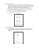
Twisted Hook Hook Swivel Figure 5-1 Top & Bottom Hook Checks Table 5-4 Top Hook & Bottom Hook Dimensions “k” Measured When New: Top: _________________________ Bottom: ______________________ Product Code Nominal "k" Dimension* inch (mm) CF005 CF010 CF015 CF020 CF030 CF050 1.76 (44.6) 1.92 (48.8) 2.22 (56.3) 2.36 (59.9) 2.72 (69.1) 3.06 (77.8) "u" Dimension inch (mm) Standard Discard 0.67 (17.0) 0.59 (15.0) 0.86 (21.8) 0.79 (20.0) 1.04 (26.5) 0.94 (24.0) 1.18 (30.0) 1.06 (27.0) 1.48 (37.5) 1.34 (34.
Table 5-6 Body Top Pin Wear Dimensions “d” Dimension inch (mm) Standard Discard Product Code CF005 0.472 (12) 0.433 (11) CF010, CF020 0.472 (12) 0.433 (11) CF015, CF030, CF050 0.630 (16) 0.591 (15) Table 5-7 Chain Pin Wear Dimensions Product Code CF005 CF010, CF020 CF015, CF030, CF050 “d” Dimension inch (mm) Standard Discard 0.244 (6.2) 0.232 (5.9) 0.311 (7.9) 0.295 (7.5) 0.343 (8.7) 0.327 (8.
Figure 5-2 Brake Assembly Table 5-9 Friction Plate Wear Dimensions Thickness inch (mm) Product Code All Standard Discard 0.118 (3.0) 0.098 (2.5) Table 5-10 Brake Bushing Wear Dimensions A Dimension Product Code inch (mm) Standard Discard CF005 0.118 (3.0) 0.079 (2.0) CF010, CF015, CF020, CF030, CF050 0.157 (4.0) 0.118 (3.
Table 5-11 Brake Ratchet Disc Wear Dimensions D Dimension Product Code inch (mm) Standard Discard CF005 3.425 (87) 3.307 (84) CF010, CF015, CF020, CF030, CF050 3.858 (98) 3.
6.0 Maintenance and Handling 6.1 Lubrication 6.1.1 Load Chain For longer life, the load chain should be lubricated. The load chain lubrication should be accomplished after cleaning the load chain with an acid free cleaning solution. Apply Harrington lubricating grease (Part No. ER1BS1951) or an equivalent to industrial general lithium grease, NLGI No. 0, to the bearing surfaces of the load chain links as indicated by the shaded areas in Figure 6-1.
6.2 Disassembly, Assembly and Adjustment 6.2.1 1) Perform proper disassembly or assembly in accordance with this manual. 2) The hoist utilizes dry friction plates; they are not to be lubricated. 3) Do not extend the load chain. 4) Remove old grease on the disassembled parts. 5) Replace components with Harrington Hoist approved parts. 6) To reassemble, apply new grease, and use a new split pin and snap ring. 6.2.2 Tools – The following tools are required to disassemble/reassemble the hoist. No.
NOTE: The pawl pin is fixed with the U nut [25]. 11) Unscrew four socket bolts [22, 22-A] connecting body A [10] and B [11]. NOTE: Four socket bolts are fixed with U nuts [23] on the body B side. 12) Separate the body A [10] and B [11]. 13) Take ball bearing A [15] and C [17-A] out of the body A [10] (only if bearing needs replaced). 14) Remove the top hook [1] and top pin [3] from the body B [11].
6) Insert the end of the load chain [42] to the bottom hook [4] and fix them with the chain pin [7], slotted nut [8] and split pin [9]. For Bullard , Shur-loc , or Inspection type hooks, refer to Table 63 for yoke nut torque specifications. : Always bend the split pin securely. Figure 6-3 Bottom Hook Assembly 7) Place the load chain [42] on the load sheave [18] so that the bottom hook side comes to right hand and the end link of the other side becomes vertical to the load sheave pocket.
Figure 6-5 Chain Guide Assembly 12) Clean and grease ball bearing A [15] and D [17-A] and insert into body A [10] (if being replaced). 13) Put the body A [10] with the ball bearings [15, 17-A] side down on the body B [11]. : Make sure each part is completely set between body A [10] and frame [13]. 14) Insert four socket bolts [22, 22-A] into the body A [10] and turn the whole body sideways. Then fix the bolts with the U nuts [23] holding the U nuts with fingers.
17) Thread friction disc [29] on the pinion [14]. 18) Wipe out any dirt on the friction disc [29], friction plates [32] and both sides of the ratchet disc [30] and make sure that bushing [31] is properly soaked with oil. Then place the friction plate, bushing, ratchet disc (while the pawl [27] is rotated counterclockwise), and friction plate respectively on the friction disc. (Make sure that the pawl meshes with the ratchet disc properly.) : NEVER apply oil since the brake is a “dry system”.
Figure 6-8 Hand Wheel Assembly 22) Put wheel cover [37] on the body A [10] and fix them with the spring washers [39] and screws [38]. 23) Put a hoist with body B [11] side up. Place the slack end of the load chain between body A [10] and body B [11]. Then insert tail pin [40], and screw tap socket bolt [41] into the body B. : Make sure the load chain is not twisted. Be careful not to cross thread or over torque tap socket bolt [41].
6.5 Storage 6.5.1 : IMPROPER chain hoist use could result in death or serious injury. To avoid these hazards: 6.6 ALWAYS store the hoist in a no load condition. ALWAYS wipe off all dirt and water. ALWAYS oil the chain, hook pins and hook latches. ALWAYS hang in a dry place. ALWAYS check the hoist for abnormalities (according to the regular inspection procedures) when using the hoist after a period of non-use (Refer to section 5.5). Outdoor Installation 6.6.
7.0 Troubleshooting Read and comply with instructions in this manual and use the hoist properly. Checking the sounds from the hoist in operation is a critical inspection. Note hoist sounds during operation. If a defect is found in the hoist, stop using it immediately and check the cause of the defect. Only Trained and competent personnel should inspect and repair the hoist.
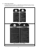
Table 7-1 Troubleshooting Guide Symptom Cause Remedy Reassemble properly and ensure proper lifting before reuse. During operation, hoist idles or load drifts Poor load sheave and load chain contact caused by improper chain-reeving. Reset the capsized hook. Hoist will not lift all the way (multiple fall hoists) Capsized hook Twisted Chain Capsized Hook and Chain Double Fall Models Hoist does not lift load smoothly. Improper assembly of gear OR bearing broken.
Table 7-1 Troubleshooting Guide Improper braking may cause improper load lowering. The hoist utilizes dry friction discs; do not apply oil to friction surfaces. Symptom Cause Remedy Over tightened brake The hoist left under load for a long period Load will not go down Pull down hard (possibly with 2 people) on the hand chain to loosen brake. Shock loaded during operation Brake rusted tight Replace the rusty components and perform hoist maintenance.
8.0 Warranty Warranty explanation and terms. All products sold by Harrington Hoists, Inc.
This Page Intentionally Left Blank 37
9.0 Parts List When ordering Parts, please provide the Hoist code number, lot number and serial number located on the Hoist nameplate (see Figure 9-1 below). Reminder: Per Sections 1.1 and 3.4.4 to aid in ordering parts and product support, record the hoist Code, Lot and Serial Number in the space provided on the cover of this manual. Figure 9-1 CF4 Nameplate The parts list is arranged into the following sections: Section Page 9.1 1/2 to 5 Ton Parts………………….…………………………………………………...……….………. 39 9.
9.
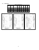
9.1 1/2 to 5 Ton Parts Fig. No. 1 2 3 4 6 7 8 9 10 11 Name Parts / Hoist 1 1 1 1 1 1 1 1 1 1 1 1 1 13 Top Hook Assembly Latch Assembly Top Pin Bottom Hook Complete Set Latch Assembly Chain Pin Slotted Nut Split Pin Body A Body B without rivets Name Plate Blank with rivets Frame 14 Pinion 1 Ball Bearing A (Fig. 14) Ball Bearing B (Fig. 14) Ball Bearing C (Fig. 14) Ball Bearing D (Fig.
9.2 Additional 2 through 5 Ton Parts Figure 9-3 Additional 2 through 5 Ton Parts Fig. No. 44 45 Parts / Hoist 2 Ton 3 Ton Top Hook Assembly 1 CF001020 CF001030 CF071030 Name Latch Assembly 1 CF071020 46 Chain Pin 1 CF041020 47 Slotted Nut for Fig. 46 1 48 Split Pin for Fig.
9.3 Optional Hooks Figure 9-3 Bullard®, Shur-Loc® and Inspection Hooks ® Bullard Hooks Parts Per Hoist 1/2 Ton 1 Ton 1 1/2 Ton Bullard® Top Hook Complete Set 1 6027601 6027602 6027603 6027606 2 Bullard® Hook Assembly 1 60160 60162 60164 60169 3 Top Yoke Kit 1 TYKITCB005 TYKITCB010 TYKITCB015 4 Button Head Screw 2 9012612 9012602 5 Flexloc® Nut** 2 9012613 9012604 6 Warning Tag 1 Fig. No.
9.3 Optional Hooks ® Shur-Loc Hooks Parts Per Hoist 1/2 Ton 1 Ton 1 1/2 Ton Shur-Loc® Top Hook Complete Set 1 6030201 6030202 6030203 2 Shur-Loc® Hook Assembly 1 60140 60142 60144 3 Top Yoke Kit 1 TYKITCB005 TYKITCB010 TYKITCB015 4 Button Head Screw 2 9012612 9012602 9012613 9012604 Fig. No.
9.
NOTES 45
NOTES 46
NOTES 47
www.harringtonhoists.com Harrington Hoists, Inc. 401 West End Avenue Manheim, PA 17545-1703 Phone: 717-665-2000 Toll Free: 800-233-3010 Fax: 717-665-2861 Harrington Hoists – Western Division 2341 Pomona Rd.