EFFECTIVE: September 27, 2010 Mini-Cat AIR POWERED CHAIN HOIST AH SERIES 250 and 500 Lb. Capacity Product Code and Serial Number This equipment should not be installed, operated or maintained by any person who has not read and understood all the contents of this manual. Failure to read and comply with the contents of this manual can result in serious bodily injury or death, and/or property damage.
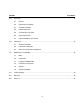
Table of Contents Section 1.0 2.0 3.0 4.0 Page Number Important Information and Warnings ……………………………………………………………………… 4 1.1 Terms and Summary 1.2 Warning Tags and Labels Technical Information………………………………………………………………………………………. 8 2.1 Specifications 2.2 Speeds, Air Consumptions and Dimensions 2.3 Part Names Pre-operational Procedures …………………………………………………………………...…………. 14 3.1 Air Supply System Requirements 3.2 Air Supply Capacity and Regulation 3.3 Lubrication 3.4 Filtration 3.
Section 5.0 6.0 7.0 Page Number Inspection ………………..………………………………………………………………………………... 28 5.1 General 5.2 Inspection Classification 5.3 Frequent Inspection 5.4 Periodic Inspection 5.5 Occasionally Used Hoists 5.6 Inspection Records 5.7 Inspection Methods and Criteria Lubrication……………………………………………………………………………..…………………... 35 6.1 Air Hoist Lubrication 6.2 Load Chain Lubrication 6.3 Hooks and Suspension Components Maintenance and Handling ………………………………………………………………………………. 36 7.1 Brake 7.
1.0 Important Information and Warnings 1.1 Terms and Summary This manual provides important information for personnel involved with the installation, operation and maintenance of this product. Although you may be familiar with this or similar equipment, it is strongly recommended that you read this manual before installing, operating or maintaining the product. Danger, Warning, Caution and Notice Throughout this manual there are steps and procedures that can present hazardous situations.
Equipment described herein is not designed for and MUST NOT be used for lifting, supporting, or transporting people, or for lifting or supporting loads over people. Equipment described herein should not be used in conjunction with other equipment unless necessary and/or required safety devices applicable to the system, crane, or application are installed by the system designer, system manufacturer, crane manufacturer, installer, or user.
It is the responsibility of the owner/user to install, inspect, test, maintain, and operate a hoist in accordance with ANSI/ASME B30.16, “Safety Standard for Overhead Hoists” and OSHA Regulations. If the hoist is installed as part of a total lifting system, such as an overhead crane or monorail, it is also the responsibility of the owner/user to comply with the applicable ANSI/ASME B30 volume that addresses that type of equipment.
1.2 Warning Tags and Labels The warning tag illustrated below in Figure 1-1 is supplied with each hoist shipped from the factory. If the tag is not attached to your hoist (for pendant and manipulator control, the warning tag is attached to the pendant hose; for the pull cord control, the warning tag is attached to the up cord), order a tag from your dealer and install it. See parts list in the parts section of this manual. Read and obey all warnings attached to this hoist. Tag is not shown actual size.
2.0 Technical Information 2.1 Specifications 2.1.1 Product Code 2.1.2 Features and General Specifications: Weight/Size : Light weight and compact size – cord model with 10 feet (3.0 m) of lift weighs 15.2 lbs. (6.9 kg). Motor Brake : Reliable disc brake system High Speed Lifting : 26 to 47 ft/min. (7.9 to 14.3m/min.
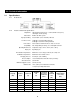
2.2 Speeds, Air Consumptions and Dimensions Table 2-2 Cord Model Speeds, ft/min at 90 psi* Capacity (lbs.) Product Code UP DOWN Full Load No Load Full Load No Load 250 AH250C 47 (37) 61 (53) 51 (47) 45 (40) 500 AH500C 32 (20) 61 (53) 56 (54) 45 (40) Table 2-3 Cord Model Air Consumption, CFM at 90 psi* Capacity (lbs.
Table 2-4 Pendant Model Speeds, ft/min at 90 psi* Capacity (lbs.) Product Code UP DOWN Full Load No Load Full Load No Load 250 AH250P 42 (33) 55 (48) 48 (45) 43 (38) 500 AH500P 29 (18) 55 (48) 53 (51) 43 (38) Table 2-5 Pendant Model Air Consumption, CFM at 90 psi* Capacity (lbs.) Product Code UP DOWN Full Load No Load Full Load No Load 28 (21) 31 (24) 27 (21) 26 (20) 500 AH500P 26 (19) 31 (24) * Values in parentheses for air supply at 60 psi.
Table 2-6 Manipulator Model Speeds, ft/min at 90 psi* Capacity (lbs.) Product Code UP DOWN Full Load No Load Full Load No Load 250 AH250M 41 (32) 54 (47) 47 (44) 42 (37) 500 AH500M 29 (18) 54 (47) 53 (50) 42 (37) Table 2-7 Manipulator Model Air Consumption, CFM at 90 psi* Capacity (lbs.
2.
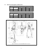
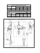
Figure 2-6 AH250M and AH500M Manipulator Model Part Names 13
3.0 Pre-operational Procedures 3.1 Air Supply System Requirements 3.1.1 3.1.2 3.1.3 3.2 Pressure and Flow - Verify that the air supply system has capacity to supply your air hoist with required pressure and flow. Otherwise the hoist may operate poorly or may fail to operate. See Section 3.2. Lubrication - The hoist requires lubrication for proper operation. The oil in the air supply is the primary source of lubrication to the hoist.
3.4 Filtration 3.4.1 3.4.2 3.5 The filter servicing the hoist can also service other hoists and air consuming equipment. In this case, the air filter must be in sized for the total air consumption of the equipment it is servicing. Air Dryer 3.5.1 3.6 The air entering the hoist inlet must not contain any particulate greater than 5 microns in size. Therefore, the hoist must have a 5 micron filter in its air supply. The filter must be upstream of the lubricator.
3.6.2 3.6.3 Supply line inside diameter - Pipes and hoses should be sized to accommodate the hoist’s airflow requirements. The inside diameter for the pipe section feeding the hoist should be 12.7mm (½”) or larger and for air supply hose the inside diameter should be 9.5mm (3/8”) inch or larger. Hoses - The connection from the air supply system piping to the hoist must be made with a flexible pressure hose.
3.8 Connecting Hoist to Air Supply 3.8.1 3.8.2 HAZARDOUS AIR PRESSURE IS PRESENT IN THE HOIST, IN THE SUPPLY OF COMPRESSED AIR TO THE HOIST, AND IN THE CONNECTIONS BETWEEN COMPONENTS. Shut off the air supply and stop the airflow completely. Lock out and tag out in accordance with ANSI Z244.1 “Personnel Protection -Lockout/Tagout of Energy Sources”. Figure 3-4 Cord Model Connection to Hoist Figure 3-5 Pendant and Manipulator Models Connection to Hoist 3.8.
3.9 Mounting the Hoist 3.9.1 Mini Trolley - Follow instructions below to install the trolley. Refer to Figure 3-6. 1) Remove the Top Hook Complete Set from the hoist and install the Suspender. 2) Refer to Table 3-1 for placement of Adjusting Spacers for the flange width “B” of the traversing beam. The position of spacers differs with flange width. If the beam flange width is not listed in Table 3-1, use the next size smaller and make adjustments in accordance with step 3.
Figure 3-6 Diagram for Mini Trolley Installation 3.9.2 Manual Trolley - Follow instructions in Owner’s Manual provided with the trolley. 3.9.3 Motorized Trolley - Follow instructions in Owner’s Manual provided with the trolley. 3.9.4 Hook Mounted to a Fixed Location - Attach the hoist’s top hook to the fixed suspension point. 3.9.5 3.10 Ensure that the fixed suspension point rests on the center of the hook’s saddle and that the hook’s latch is engaged. Optional Chain Container 3.10.
Figure 3-7 Chain Container Installation 3.11 Non-Stationary Application 3.11.1 For applications such as rental fleets or construction sites where the hoist is moved from place-to-place, a filter and lubricator are still required. Consult factory for recommended methods. 3.11.2 Connections and fittings must be kept clean and care taken to prevent dirt, debris and moisture from entering the hoist. 3.11.
Right-Hand Left-Hand Figure 3-8 Converting Manipulator Model Between Right and Left-Hand Operation. 3.13 Manipulator Model’s Bottom Hook Position 3.13.1 The Bottom Hook can be extended below the manipulator control to allow for easier load attachment and operation as required by the application. Follow instructions below. Refer to Figure 3-9. 1) Run the hoist in the down direction until there is a sufficient amount of Load Chain below the hoist.
Standard Alternate/Extended Figure 3-9 Manipulator Model’s Bottom Hook Position 3.14 Preoperation Checks and Trial Operation 3.14.1 3.14.2 Confirm the adequacy of the rated capacity for all slings, chains, wire ropes and all other lifting attachments before use. Inspect all load suspension members for damage prior to use and replace or repair all damaged parts. Verify that the no-load end of the load chain is attached to the hoist body. For reference see Figure 7-3. 3.14.
3.14.6 If hoist is installed on a trolley, ensure that trolley is properly installed on the beam, and stops for the trolley are correctly positioned and securely installed on the beam. 3.14.7 Ensure that all nuts, bolts and split (cotter) pins are sufficiently fastened. 3.14.8 For Pendant model hoists, ensure that the Pendant Hoses/Tubes are properly attached to the hoist and Pendant Valve CP. See Section 7.3. 3.14.
4.0 Operation 4.1 Introduction DO NOT WALK UNDER A SUSPENDED LOAD HOIST OPERATORS SHALL BE REQUIRED TO READ THE OPERATION SECTION OF THIS MANUAL, THE WARNINGS CONTAINED IN THIS MANUAL, INSTRUCTION AND WARNING LABELS ON THE HOIST OR LIFTING SYSTEM, AND THE OPERATION SECTIONS OF ANSI/ASME B30.16 and ANSI/ASME B30.10. THE OPERATOR SHALL ALSO BE REQUIRED TO BE FAMILIAR WITH THE HOIST AND HOIST CONTROLS BEFORE BEING AUTHORIZED TO OPERATE THE HOIST OR LIFTING SYSTEM.
The operation of an overhead hoist involves more than activating the hoist’s controls. Per the ANSI/ASME B30 standards, the use of an overhead hoist is subject to certain hazards that cannot be mitigated by engineered features, but only by the exercise of intelligence, care, common sense, and experience in anticipating the effects and results of activating the hoist’s controls.
Improper operation of a hoist can create a potentially hazardous situation which, if not avoided, could result in minor or moderate injury, or property damage. To avoid such a potentially hazardous situation THE OPERATOR SHALL: • Maintain a firm footing or be otherwise secured when operating the hoist. • Use the hoist manufacturer’s recommended parts when repairing the unit. • Check brake function by tensioning the hoist prior to each lift operation.
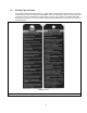
4.4 Controlling Hoist Speed 4.4.1 For the cord control, adjust the speed by varying the amount of pull on the cord. Refer to Figure 4-2. Figure 4-2 Cord, Pendant and Manipulator Control Speed Adjustment 4.4.2 For the pendant or manipulator control, adjust the speed by varying the amount the lever is depressed. As shown in Figure 4-2, by depressing the lever slightly, you will be able to control the hoist’s motions slowly and with more precision.
5.0 Inspection 5.1 General 5.1.1 5.2 The inspection procedure herein is based on ANSI/ASME B30.16. The following definitions are from ANSI/ASME B30.16 and pertain to the inspection procedure below. Designated Person - a person selected or assigned as being competent to perform the specific duties to which he/she is assigned.
5.3 Frequent Inspection 5.3.1 Inspections should be made on a FREQUENT basis in accordance with Table 5-1, “Frequent Inspection.” Included in these FREQUENT Inspections are observations made during operation for any defects or damage that might appear between Periodic Inspections. Evaluation and resolution of the results of FREQUENT Inspections shall be made by a designated person such that the hoist is maintained in safe working condition.
5.5 Occasionally Used Hoists 5.5.1 5.6 5.7 Hoists that are used infrequently shall be inspected as follows prior to placing in service: Hoist Idle More Than 1 Month, Less Than 1 Year: Inspect per FREQUENT Inspection criteria of Section 5.3 above. Hoist Idle More Than 1 Year: Inspect per PERIODIC Inspection criteria of Section 5.4 above. Inspection Records 5.6.
Table 5-3 Hoist Inspection Methods and Criteria Item Method Criteria Action Hooks - Bent Shank or Neck Visual Shank and neck portions of hook should be free of deformations Replace. Hooks - Yoke Assembly Visual Should be free of significant rust, weld splatter, nicks, gouges. Holes should not be elongated, fasteners should not be loose, and there should be no gap between mating parts. Clean/Lubricate, or replace as required.
Table 5-3 Hoist Inspection Methods and Criteria Item Method Criteria Action Chain Separator Visual, Measure The Chain Separator should be free of cracks, distortion, significant wear and corrosion. The “L” and "W" dimension should not be greater than maximum value listed in Table 5-5. Replace Motor Brake Measure, Visual Motor brake dimension should be within the allowable limits of Table 5-4. See Section 7.1 for gaining access to motor brake.
Table 5-4 Brake Disc Dimension “T” Dimension Parts List Fig. No. Hoists AH250C AH250P AH250M AH500C AH500P AH500M inch (mm) 72 Standard Discard 0.31 (8) 0.29 (7.3) Table 5-5 Chain Separator Dimensions Hoists AH250C AH250P AH250M AH500C AH500P AH500M Parts List Fig. No. 92 “L” Dimension “W” Dimension inch (mm) inch (mm) Standard Discard Standard Discard 0.33 (8.5) 0.41 (10.5) 0.61 (15.5) 0.69 (17.
Table 5-6 Top Hook & Bottom Hook Dimensions Dimensions K and U should be measured and recorded below prior to any use when the hook is first placed into service. Hoists Parts List Fig. No. AH250C AH250P AH250M AH500C AH500P AH500M “K” Dimension “U” Dimension inch (mm) inch (mm) Recorded Dimension When New 140a Top Hook K = ____________ 142a Bottom Hook K = ____________ Maximum /Minimum Value for Discard For K if the measured dimension exceeds K(new) + 0.5mm, the hook should be replaced.
6.0 Lubrication 6.1 Air Hoist Lubrication 6.1.1 6.1.2 6.1.3 6.2 6.3 See Section 3.0 for lubrication requirements. Lubrication to the motor will be provided primarily by the air supply lubricator. The recommended amount is 10-15 drops/minute (2-3cc/min.). Refer to Table 6-1 below for the approved lubricant for use with your air hoist. Additional lubrication to the reduction gears is not necessary.
7.0 Maintenance and Handling 7.1 Brake 7.1.1 The hoist brake is not adjustable. 7.1.2 Inspect the brake disc in accordance with Section 5.7, Table 5-3. 7.1.3 The following is the hoist brake inspection procedure. Refer to Figure 7-1. 1) HAZARDOUS AIR PRESSURE IS PRESENT IN THE HOIST, IN THE SUPPLY OF COMPRESSED AIR TO THE HOIST, AND IN THE CONNECTIONS BETWEEN COMPONENTS. Shut off the air supply and stop the airflow completely. Lock out and tag out in accordance with ANSI Z244.
7.2 Load Chain 7.2.1 Lubrication and Cleaning Clean the chain with an acid-free cleaning solution. The load chain should be kept clean and lubricated. 7.2.2 Lubrication - Clean and lubricate the load chain per Section 6.0 at least once every 3 months for normal usage. Clean and lubricate more frequently for heavier usage or severe conditions. Replacement 1) 2) An air supply line must be connected to the hoist in order to perform the following procedures.
Figure 7-2 Load Chain Installation Diagram Figure 7-3 Chain Connections 38
7.3 Pendant and Manipulator 7.3.1 The following procedure covers the installation of the molded tubing version of the Pendant Hose (Parts List Figure Number 154) and the Pendant Valve CP. Refer to Figure 7-4. 1) Place boots on the ends of the Pendant Hose. 2) Firmly press the individual color-coded pendant tubes completely into the Tube Fittings on the Pendant Valve CP and Manifold Block until they bottom out. Refer to Figure 7-4 for the correct placement of the tubes.
Figure 7-5 3-Hose Pendant Connections 7.3.3 The following procedure covers the installation of the Coil Hose (Parts List Figure Number 202) onto the Manifold Block and Manipulator Control. Refer to Figure 7-6. 1) Insert all 3 hoses through the large opening in the Hose Support. Slide the Hose Support around approximately 1 coil of the hose. 2) At the hoist, insert all 3 hoses through the Hose Arm attached to the hoist body then insert the Down Tube through the small opening in the Hose Support.
Figure 7-6 Manipulator Hose Connections 7.4 Load Sheave Inspection 7.4.1 Perform this inspection by removing the chain separator and viewing the load sheave while operating the hoist slowly, with no load, and in accordance with Section 4 “Operation”. Refer to Figure 7-7 and remove the chain separator as follows: 1) An air supply line must be connected to the hoist in order to perform the following procedures. 2) Remove the 2 Button Head Screws attaching the chain lever to the limit shaft.
Figure 7-7 Load Sheave Inspection 7.5 7.6 Storage 7.5.1 Whenever the hoist is to be placed into storage, place extra lubricating oil into the air inlet opening and circulate the air motor before plugging the inlet. Make certain that no debris, dirt or moisture is allowed to enter the air hoist through air inlet opening during preparations for storage. 7.5.2 The storage location should be clean and dry. Outdoor Installation 7.6.
8.0 Troubleshooting HAZARDOUS AIR PRESSURE IS PRESENT IN THE HOIST, IN THE SUPPLY OF COMPRESSED AIR TO THE HOIST, AND IN CONNECTIONS BETWEEN COMPONENTS. Before performing ANY maintenance on the equipment, de-energize the supply of compressed air to the equipment, and lock and tag the supply device in the de-energized position. Refer to ANSI Z244.1, “Personnel Protection - Lockout/Tagout of Energy Sources.” Only Trained and competent personnel should inspect and repair this equipment.
Table 8-1 Troubleshooting Guide Symptom Cause Valve Spring broken Main Spool leaking Valve in Pendant Valve CP stuck Remedy Inject approx. 20 drops of oil into inlet port to lubricate the main spool. If spool still sticks, repair at service facility. Repair at service facility Repair at service facility Repair at service facility Brake is not holding. Repair brake at service facility. Motor Vanes leaking. Replace motor Vanes at service facility. Mis-connected Pendant Hose assembly.
9.0 Warranty Warranty explanation and terms. All products sold by Harrington Hoists, Inc.
This Page Intentionally Left Blank 46
10.0 Parts List When ordering Parts, please provide the Hoist code number and serial number located on the Hoist nameplate (see Figure 10.1 below). Reminder: Per Sections 1.1 and 3.14 to aid in ordering Parts and Product Support, record the Hoist code and serial number in the space provided on the cover of this manual. Figure 10 -1 AH Name Plate The parts list is arranged into the following sections: Section 10.1 10.2 10.3 10.4 Page Main Body……………………………………………………………….……………………………........
10.
Main Body Figure Number Name Parts Per Hoist Part Number Figure Number Name Parts Per Hoist Part Number 50 Motor Case 1 AH426205790 118 Lock Screw 1 AH426205890 51 Rear Plate 1 AH426205180 119 Brake Plate 1 AH426205900 52 Cylinder 1 AH426205160 120 Bearing 2 9001206 53 Rotor 1 AH426205150 121 Bearing 2 AH130113003 54 Front Plate 1 AH426205170 122 Needle Bearing 6 AH130170013 55 Vane 6 AH137102018 123 O-Ring 1 AH131103047 56 Knock Pin 1 AH130402049
10.
Valve Body Figure Number Name Cord Model Only: Parts Per Hoist Part Number Figure Number Name Parts Per Hoist Part Number AH426205060 1 Main Spool 1 AH426205010 2 Valve Bush 1 AH426205780 6 Valve Body 1 3 Shuttle 1 AH426205870 20 Valve Spring 1 AH130802208 4 Valve Seat R 1 AH426205830 34 Hex Socket Pipe Plug 1 TCR134902003 5 Valve Seat L 1 AH426205840 160 S-Type Wire 2 TCR130802081 7 Side Cover 2 AH426205080 161R Red Cord (Down) ft (m) 9013102 8 Valve Pin
10.
Manipulator Control Figure Number 12M Name Chain Basket CP Parts Per Hoist Part Number Figure Number Name Parts Per Hoist Part Number 1 AH42621592C 240 Button Head Screw 1 AH131905060 1 pr.
10.
Optional Components Mini Trolley: Figure Number Name Parts Per Trolley Part Number 1 Name Plate C 1 ET25801525 2 Name Plate B 1 ET25800525 3 Track Wheel Assembly 4 ET255102525 4 Slotted Nut 4 M2049010 5 Split Pin 4 9009411 6 Socket Bolt 2 ET25115525 7 Adjusting Spacer 32 ET25116525 8 Nut 2 9093424 9 U-Nut 2 ET25155525 10 Split Pin 2 9009411 11 Suspender 1 60456 Chain Containers for Cord and Pendant Models*: Parts Per Hoist 10 ft Max. Lift 20 ft Max.
www.harringtonhoists.com Harrington Hoists, Inc. 401 West End Avenue Manheim, PA 17545 Phone: 717-665-2000 Toll Free: 800-233-3010 Fax: 717-665-2861 Harrington Hoists - Western Division 2341 Pomona Rd.