HARMONIC RESOLUTION SYSTEMS SXR AUDIO STAND
Discover Your System’s Capability
Introduction Thank you for purchasing the Harmonic Resolution Systems SXR Audio Stand. When used properly, it will give you many years of superior musical or video signal reproduction. The SXR Audio Stand significantly reduces the negative impact of structure-borne noise on your audio or video component performance. Decades of engineering experience, custom material development, and listening tests are incorporated into the design of the SXR Audio Stand.
Safety Instructions IMPORTANT WARNINGS! Do not place any tall objects on the top shelf of the SXR Audio Stand. A tall object is any object with a height that is greater than the length of the isolation base. A tall object is also any object that has a height greater than its own width or length. Tall objects must not be placed on top of the SXR Audio Stand for any reason. The object may become unstable and tip over causing damage to the component, adjacent objects, or injury to people.
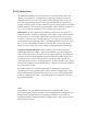
Set-Up Instructions The SXR Audio Stand consists of a frame structure and the isolation bases that support each component. The components required to assemble the frame are shipped in one or more boxes. The number of boxes depends on the system size. Each box containing parts for the frame will be marked with the model number starting with SXR. All the wrenches required to put the frame together are included with the shipment. The only tools not provided that will be useful for assembly is a level.
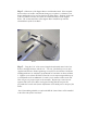
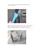
Step 1. Obtain one of the Support Braces with threaded studs. Place it upside down on the work surface with threads facing up (see photo 1). Obtain a Cross Brace and flip this over as well as shown in the photo below. Slide one of the ends of the Cross Brace into the area below the countersunk holes on the Support Brace. The countersunk holes of the Support Brace should line up with the threaded holes of the Cross Brace. Photo 1 Step 2.
Note: Be very careful not to cross-thread the threaded struts or fasteners. They should thread in very easily. If it does not, back it out and start it in again (repeat as necessary). Never force a threaded connection. If it does not thread on easily then there is something wrong and you should contact HRS or your local retail facility for assistance. Apply proper torque when instructed and after all the fasteners at each step are in place.
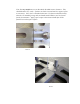
Step 3. Slide a polymer ring over each of the threaded studs on the Support Brace as shown in Photo 4. Push down until the polymer ring is seated in the groove on the Support Brace. Photo 4 Step 4. Apply 4-5 drops of the 3-in-1 oil to the top few threads of each of the six threaded studs as shown in Photo 5. If assembling a SXR-1V (one high stand or amp stand) go to Step 10. If not continue with next step.
Photo 5 Step 5. By hand screw the struts onto the threaded studs as shown in Photo 6. If you have a stand with different size struts keep in mind that you are building the stand upside down. The struts you are installing now are the struts that will become the struts between the top and second shelf when the stand is completed. Note: Shelf spacing is approximately 3” less than the strut length. Verify you have the correct strut length required for your system.
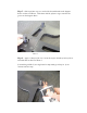
Note: it is important to get proper torque on struts to achieve proper frame stiffness and performance. Photo 7 Step 7. Slide a polymer ring over the threads of each of the struts. Be sure the polymer ring is seated fully on the strut as shown in Photo 8 (the polymer ring should sit on the non-threaded shoulder just below where the thread stops.
Note: If your SXR came partially assembled please make sure that in Step 8 the 1/4” - 20 x 3/4” flat head cap screws must be loosened 1/4 turn before proceeding to Step 9. Step 8. Refer to steps 1 and 2 to build another Support/Cross Brace subassembly as shown in Photo 9. However this time each screw should be finger tight and then loosen by turning the Allen wrench 1/4 turn counterclockwise. Photo 9 Step 9.
10 At this point the screwsPhoto connecting the Cross Brace sub assembly should be fully tightened. Before tightening screw fully be sure that the Cross Brace and Support Brace are completely perpendicular to each other as shown in Photo 2. Tighten screws (shown in Photo 3) until the screws stop turning and the top of T-Wrench handle twists an additional 1/16 to 1/8 of a rotation relative to the bolt. This will give you proper torque on the assembly.
Photo 11 As done in Step 4 - add 3-4 drop of oil to each of the threads of the struts. If your SXR requires another layer to be added repeat Steps 5 to 9. Note when building the additional layers you should torque the struts in a sequence going to one half turn (past snug) on each strut and then through the sequence again to obtain the full rotation (past snug). Step 10. After placing the Polymer Ring over each of the threaded struts.
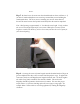
Note: it is important to get proper torque on each Strut and the Locking Nuts to achieve proper frame stiffness and performance. Photo Step 12. Screw the 13 Washer onto the threads of the struts completely as shown in Photo 14. Screw all the way down until the Washer comes in contact with the Locking Nut. Light hand tight is fine. Do not put a large torque on Washer. Photo 14 Step 13. Screw the Stand Points onto the threads of the struts completely as shown in Photo 15.
Step 14. At this Photo point the SXR Frame is completely assembled. Flip the SXR Frame upright as shown in Photo 16. Move the frame to the exact final location for use in your system. Make sure the front of the frame is the side with the HRS logo on the Cross Brace facing into the room. You are now ready to level the SXR frame. Place a level on the top Cross Brace.
Photo 16 Isolation Base Installation into SXR Frame - Uncrate each of the isolation bases if not already complete. Make sure you read and follow all of the instructions in the isolation base manual prior to installing into the SXR Audio Stand frame. You will want to verify that the frame size matches the isolation base size. The SXR1921 uses the 1921 isolation bases. The SXR-1719 uses the 1719 isolation bases. Match the load range of each isolation base with the component weight.
Photo 17 Photo 18 Completed SXR Singlewide3V version on left, and Doublewide 3V version on the right. Both system shown with M3 Isolation Bases. Loading Components into SXR Frame - Carefully load each component into the SXR Audio Stand. Be careful not to hit the front edge of the isolation base because you will scratch the frame. Once all the components are loaded, you should check to see that none of the isolation bases are overloaded.
Please follow the care instructions in the isolation base manual to clean and care for the shelves (isolation bases) of the SXR Audio Stand. Read and follow the instructions received with the isolation base to ensure optimum performance and cosmetic appeal. Do not spray, soak, or submerge the rack frame or isolation bases in water or cleaning solutions. The rack system and isolation bases are made from many different parts and materials.
Warranty Limited Five Year Warranty Harmonic Resolution Systems warrants to the purchaser that each HRS SXR Audio Stand is free of manufacturing defects for a period of five (5) years from the date of purchase. This warranty is subject to the following conditions and limitations. 1. A copy of the original purchase receipt from a certified Harmonic Resolution Systems authorized retailer is used to verify the date of original purchase and ownership. 2.
HARMONIC RESOLUTION SYSTEMS INC. 2495 Main Street, Suite 355 Buffalo, NY 14214 Telephone: 716-873-1437 Web: www.avisolation.com E-mail: info@avisolation.