Installation & Operating Manual VF3000 Coal Stoker Boiler SAFETY NOTICE Please read this entire manual before you install and use your new room heater. Failure to follow instructions may result in property damage, bodily injury, or even death. FOR USE IN THE U.S. only. NOT SUITABLE FOR INSTALLATION IN MOBILE HOMES IF THIS boiler IS NOT PROPERLY INSTALLED, A HOUSE FIRE MAY RESULT. FOR YOUR SAFETY, FOLLOW INSTALLATION DIRECTIONS. INSTalLATION should be performed by a qualified installer.
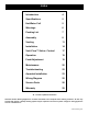
Index Introduction 4 Specifications 5 Hot Water Coil 5 Warnings 6 Packing List 7 Assembly 8 Venting 11 Installation 14 Verti-Flow™ Stoker Control 17 Operation 19 Feed Adjustment 19 Maintenance 20 Troubleshooting 22 Aquastat Installation 23 Wiring Diagram 25 Service Parts 26 Warranty 29 = Contains updated information Harman® Central Heating Appliances are built and tested to be complete Home Heating solutions.
Introduction The VF 3000 Stoker Boiler features our patented Verti-Flow™ Coal Feeder. The VF 3000 has a 5,000 to 95,000 BTU range and 250 lb. coal hopper capacity. An aquastat is used to activate the feeder when more heat is needed to maintain the set water temperature. When the Aquastat senses the water is at the set temperature the feeder stops feeding coal. Now the Verti-flow™ Stoker Control takes over to maintain a very low fire until more heat is needed.
Specifications/Hot Water Coil Hot Water Coil To install a hot water coil: 1. Remove the blank plate covering the water coil opening. 2. Insert the coil into the boiler as shown. Be sure to put a new gasket around the coil plate. 3. Tighten all bolts evenly. 4. Fill the boiler and check for leaks before and after the boiler is up to temperature. Rust caused by a leak can reduce the life of the boiler. 5.
Warnings Never sleep in the same room with any coal burning stove. Always empty the hopper when not burning for more than a week. When left standing for long periods with wet coal, the pusher block will rust and corrode, causing it to seize. If the stoker is then turned “on”, damage to the pusher assembly and feed motor will result. This will be considered neglect and will void the warranty on those parts.
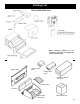
Packing List NOTE: Although required for unit completion, the Feeder and Hopper are sold as separate items.
Assembly Top Left Side Hopper Support Front Door Blank Boiler Hopper - Sold separately Cleaning Rod Spring Handle Adapter Plate Right Side Baffle Clean out slide Base Jacket Flue Pipe Base Ash Tub Flue Plate Ash Door The VF3000 is reversible as to which end the hopper and flue pipe are located. Therefore, a decision must be made as to which way will work best for your situation.
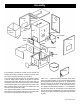
Assembly Hopper right, flue left Hopper left, flue right Feeder Begin assembly by sliding the pusher block with the adjuster rod from the front through the slot shown in Fig. 1. Be sure the pusher block is turned with the bolt hole to feed indicator side. Next, hold pusher block in the most rearward position and slide the adjuster tube over the adjuster rod until it bottoms out on the pusher block. Thread the adjuster, then the wing nut on the end of the adjuster rod.
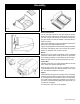
Assembly Fig. 4 Fig. 3 Snug these bolts only. Grates and Firebrick Lay the two grate inserts into the grate holder as shown. Divide the spaces between the grates equally and be sure they are not tight. The spaces are needed for expansion. The grate inserts can also be installed or removed after the feeder is in place. Place the two firebricks on the grate angle and make the two bolts snug on the adapter plate as shown.
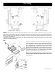
Venting Chimney Connectors and Chimneys Draft Draft is widely misunderstood. It is important that you, the stove operator, realize that draft is a variable effect, not a given quantity. Stoves and chimneys do not have draft, yet draft is the key to your stove’s performance. Draft is a force, produced by an operating stove and the chimney to which it is attached. It is created by hot gases rising up the chimney, creating a pressure difference between the inside of your home and the outside air.
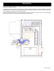
Venting Minimum 2" (50mm) Clearance to Brick Closest Combustible Material Liner Chimney Flue Hole with a minimum clearance of 18" (450 mm) between connector and wall. Non-combustible cover, one side only. If two covers are used, each must be mounted on non-combustible spacers at least 7/8" (21mm) away from the wall. Minimum 12" (300mm) to Brick Fire Clay Thimble Chimney Connector Masonry Chimney Built to NFPA 211 Specifications.
Venting Existing Masonry Chimneys If you plan on using a pre-existing masonry chimney, have it thoroughly inspected and cleaned. Any faults which make the chimney unsafe and unusable must be repaired prior to use. These can include improper height, structural defects, blockages, inadequate clearance to combustibles, unsealed openings into other rooms of the house, signs of creosote or smoke leakage, a loose or absent clean-out door, or absence of a liner.
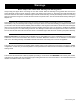
Installation Aquastat and Wiring See page 23 for assembly and mounting details. Pay close attention to the jumper positioning inside the A350 and S350 controls. Also note the sensor and its wire length when considering the mounting location. Remember that 212° f. is boiling temperature and must be avoided. Be sure to incorporate a means for flowing water in the event of an over-heat condition. Coal can not just stop burning when there is no demand for heat.
Installation Basic Plumbing This is a basic plumbing hook up. Your system may vary depending on many factors. Therefore, we recommend having experienced personnel do the plumbing. This is only one of many layouts possible. Cirulator pumps, zone valves, and thermostats are not supplied with the unit because the amount and type of these parts vary with every system. It is best to have a professional plumber do the job.
Installation Clearances Installation Place the boiler a minimum of 18” from a wall. The flue pipe must be at least 18” from anything combustible. The rear of the hopper should be a minimum of 36” from the wall. The boiler should be placed on a non-combustible floor. Secure all chimney connector pipe joints with a minimum of 3 sheet metal screws. Draft Test Procedure Attach a draft meter to the vent pipe on the boiler side of the barometric damper (if installed).
Verti-Flow™ Stoker Control 0.75 A MAX LOAD 1.25 A MAX LOAD COMPONENT RECEPTACLES - ON SIDE 0.5 A MAX LOAD VERTI - FLOW STOKER CONTROL TM Verti-Flow™ Stoker Control This section describes the features and operations of the Harman® Verti-Flow™ Stoker Control. The timers are adjustable from 0 minutes to 15 minutes in 1 minute steps. There are red lights on the front panel to show proper operation of the timer. One indicator shows power is applied to the unit.
Verti-Flow™ Stoker Control The Verti-Flow™ Stoker Control How to operate the Stoker Control The top receptacle (0.5 A) provides power to the coal feeder motor. Thus, the plug from the coal feeder motor should be inserted into this receptacle. There are four operator interfaces on the Stoker Control. The operator interfaces are: one (1) rocker switch and three (3) 16-position rotary switches. The center receptacle (0.75 A) provides power for the combustion blower motor.
Operation Fill the boiler and plumbing system with water prior to lighting! Starting a fire Feed Indicator Fill the hopper with rice coal. With the aquastat calling for heat, the coal will begin to feed onto the grate inside the stove. This process can be accelerated by adjusting the feed rate to the maximum position.
Maintenance Spring handle Ash Removal With each hopper of coal that is burned, approximately one ash pan full of ashes must be removed. Failure to remove ashes will result in a blocked grate and the fire will not burn properly. Remember, the ash pan will be hot, so always wear protective gloves. Ashes should be placed in a metal container with a tight fitting lid.
Maintenance Annually: The end of the heating season is the best time to perform annual maintenance. Rust and corrosion can form much faster in the high humidity of summer, so cleaning your VF 3000 will prevent those damages. 1. Remove all coal from the hopper 2. Remove all ashes 3. Remove and clean flue pipe 4. Check chimney and clean if necessary 5. Remove hopper and check for rust at bottom edges.
Troubleshooting Feeding Problems Gas Odor Problems Wet Coal: Wet coal does not flow the same as dry coal, therefore; the feed rate will change with wet coal. If it is too wet, it may not feed at all. Wet coal can also cause a sulfur odor. Gas Alarm Goes Off or Sulfur Odor Exists: A sulfur smell may be noticed when a door is opened during operation with wet or damp coal. This is normal.
AQUASTAT INSTALLATION AQUASTAT INSTALLATION (a350My350, s350) 1. Lay the din rail on a flat surface with the flat side down. Secure one end clamp on the left side. 2. From the right side, slide the A350 control onto the din rail. Slide the control to the left until it is against the end clamp. 3. Repeat Step 2 with the Y350 power module, connecting it to the A350 control. NOTE: Be careful when fastening the plug-together connecters located at the top of the controls. 4.
AQUASTAT 3-90-70741R13_05/13
Wiring Diagram & Fuel Coal Approved For Use With Anthracite Rice Coal Only. Anthracite coal is “hard coal”, mined primarily in the northeast United States. Rice coal, as shown at right, is typically described as coal having no dimension larger than 3/8”. Other size coal may cause feeding problems, and is therefore not recommended for use in your VF3000. It is best to buy your supply of coal when the temperature is above freezing.
VF3000 Service Parts Beginning Manufacturing Date: N/a ending Manufacturing date: active Coal Stoker Boiler 1-70-03241 1 3 2 IMPORTANT: THIS IS DATED INFORMATION. When requesting service or replacement parts for your appliance please provide model number and serial number. All parts listed in this manual may be ordered from an authorized dealer.
VF3000 Service Parts Beginning Manufacturing Date: N/a ending Manufacturing date: active #4 Feeder assembly 4.18 4.1 4.20 4.19 4.16 4.17 4.14 4.15 4.3 4.2 4.13 4.4 4.5 4.6 4.12 4.7 4.8 4.9 4.10 4.11 IMPORTANT: THIS IS DATED INFORMATION. When requesting service or replacement parts for your appliance please provide model number and serial number. All parts listed in this manual may be ordered from an authorized dealer. IteM 4.
VF3000 Service Parts Beginning Manufacturing Date: N/a ending Manufacturing date: active IMPORTANT: THIS IS DATED INFORMATION. When requesting service or replacement parts for your appliance please provide model number and serial number. All parts listed in this manual may be ordered from an authorized dealer.
Warranty hearth & home technologies lIMIted lIFetIMe warrantY Hearth & Home Technologies, on behalf of its hearth brands (”HHT”), extends the following warranty for HHT gas, wood, pellet, coal and electric hearth appliances that are purchased from an HHT authorized dealer.
Warranty warrantY COndItIOnS: • • • • • This warranty only covers HHT appliances that are purchased through an HHT authorized dealer or distributor. A list of HHT authorized dealers is available on the HHT branded websites. This warranty is only valid while the HHT appliance remains at the site of original installation. This warranty is only valid in the country in which the HHT authorized dealer or distributor that sold the appliance resides. Contact your installing dealer for warranty service.
Date Of Service Service & Maintenance Log Performed By Description Of Service 3-90-70741R13_05/13
Date Of Service Service & Maintenance Log Performed By Description Of Service 3-90-70741R13_05/13
At Harman®, we build each product to a standard, not a price. (Signature of Boxer) Your premium quality hearth product designed and assembled by the experienced and skilled members at Harman® in Halifax, PA, USA.