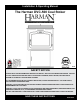
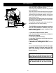
Installation & Operating Manual The Harman DVC-500 Coal Stoker R18 SAFETY NOTICE Please read this entire manual before you install and use your new room heater. Failure to follow instructions may result in property damage, bodily injury, or even death. SUITABLE FOR INSTALLATION IN MOBILE HOMES. IF THIS HARMAN STOVE IS NOT PROPERLY INSTALLED, A HOUSE FIRE MAY RESULT. FOR YOUR SAFETY, FOLLOW INSTALLATION DIRECTIONS.
Please copy your serial number from the label on your stove to the box below. nUMBERbacked metal label. 5.5” sERIAL X 7.5” adhesive LISTED SOLID FUEL BURNING ROOM HEATER - MODEL: “DVC 500” Serial No. No de série: TESTED TO: ASTM E1509, and parts of UL127 TEST DATE: July, 1996 APPROVED FOR USE IN MANUFACTURED HOMES. 008 BARCODE LABEL PREVENT HOUSE FIRES: KeeP all dOOrs and HOPPer lid ClOsed during OPeratiOn. install and use Only in aCCOrdanCe witH manufaCture’s installatiOn and OPerating instruCtiOns.
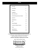
Index Warnings 4 Introduction Assembly Installation 6 Direct Vent Pipe DVC500 Microprocessor Control Operation 5 7 14 15 17 Maintenance 19 Fuel Wiring Diagram 23 25 Control and Safety Sensors 26 Parts 27 Specifications Troubleshooting 30 31 Please read this entire manual before you install and use your new room heater. Failure to follow instructions may result in property damage, bodily injury, or even death.
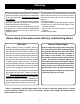
Warnings Carbon Monoxide (CO) Awareness Carbon monoxide, referred to as CO, is a colorless, odorless gas that is produced during combustion of coal and other fuels. CO fumes are toxic and can be fatal. The DVC 500 is a closed loop system specially designed to prevent the escape of CO and other combustion products from the stove. Even though this stove is designed to be as safe as possible, it is important that you install a CO detector. This is true for oil, gas, or wood burning products as well.
Introduction This remarkable design by Harman features the Verti-flow Direct Vent Stoker System. This unique, high efficiency unit uses only outside air for combustion. Micro-processor controls provide for an automatic wide range of heat output from 7,000 to 75,000 BTU . With a big 93 pound hopper capacity, this unit can burn on high approximately 16 hours or extend for over 96 hours on low.
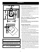
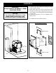
Assembly 1. Install the hopper latch as shown at left. 2. Install 3 firebricks on the cast iron angle behind the grate as shown. 3. Cement in grates as shown below. This may already be done at the factory. 3 Bricks Grate Inserts fig.
Viewing glass The glass in your Harman stove is a special ceramic glass. • Do not abuse the glass by striking or slamming the door. • Never burn the appliance if the door glass is cracked or broken. • Replace only with Harman supplied glass. Soot and/or fly-ash may accumulate on the viewing glass, and will ocassionally need to be cleaned. Clean the glass with a soft cloth and mild glass cleaner. Do not spray cleaner on hot glass, and avoid the use of abrasive cleaners.
Installation Tips On Installation Before the positioning of the unit can be decided a few questions should be considered? 1. Can the unit be vented properly and installed safely? 2. Will exhaust be vented where fumes can build up or be drawn into lower levels of the structure 3. Will fumes and fly ash affect the exterior of the structure or surrounding structures? 4. Are there any local regulations governing the use and placement of the unit? 5.
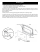
Installation 8. Complete any other exterior flue piping necessary, using 4" pellet venting. 9. Back inside, place the 2 halves of the interior wall trim plate over flue pipe. Using the black pop rivets, fasten together, then slide it against the wall and fasten it to the wall. 10. Replace the side door / rear cover assembly with 6 black screws. WARNING: DO NOT INSTALL IN MOBILE HOME SLEEPING ROOM CAUTION: THE STRUCTURAL INTEGRITY OF THE MOBILE HOME FLOOR, WALL, AND CEILING/ROOF MUST BE MAINTAINED. 11.
Installation 10
Installation Basement Installation To install a DVC 500 in a basement you will need additional DVC vent sections. These sections are made with a 316-grade stainless steel liner and a 20 gauge galvaneeled outer shell. Each joint is sealed with a gasket and is bolted together with 4 bolts. In order to maintain the best seal, there are no adjustable sections. There are straight, 45 degree, and Tee fittings. Refer to Page 14 for all of the sections available.
Installation 12
Installation 13
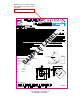
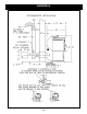
Vent Pipe Harman Direct Vent Coal Flue Pipe Venting System 1" Clearance to Combustibles Exterior Termination for wall thickness up to 8 inches 9-5/8" Gasket 45° 12" 1-10-08314 1-10-08313 3-44-06256 1-10-08310 "T" 13" 9" 6" 1-10-08315 8-3/4" 1-10-08317 1-10-08321 Joint Cover 8" 12" 1-10-08316 47" 1-10-08320 37" 11" 1-10-08326 27" 1-10-08319 10" 1-10-08324 Exterior Termination for wall thickness up to 16 inches 1-10-08323 1-10-08322 Spacer 3/16" 1-10-08318 Exterior Termination fo
ESP Control Feed Adjuster Sets the maximum feed rate, 1 to 5 Power Light Indicates power is "on" to the control. Test Runs all motors at full speed for two minutes to check operation. After two minutes the feeder stops and the distribution blower alternates from high to low every four seconds to remind you that you are still in "Test Mode". Status Light Will be lit in either Stove or Room Temp Mode when pointer is not within "off" position band except after normal shut down.
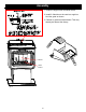
Hopper Lid Latch ESP Control Glass Door Latch Handle Side Panel Latch Ash Door Latch Handle
Operation Testing Operation: Turn the Feed Adjuster to "Test" mode, (fig. 13.) This will cause all motors to run 100% for 2 minutes. The lights on the control panel will be lit for each motor. If you leave it on "test" the blowers will cycle as an audible reminder. fig. 13 Starting Fire: 1. Fill the hopper with dry coal. NOTE: Remove all coal from hopper ledge. (fig 17) 2. Fill burn-grate area from firebrick to front of grate with about one inch of (DRY) coal. 3.
Operation Fig. 16 Keep coal off ledges Fig 17 When to use "Stove Temp Mode" In "Stove Temp Mode" the control will regulate the fire to match a constant exhaust temperature, based on the #1 thru 7 settings on the inner portion of the temp dial. Heat output and fuel consumption will remain constant. This makes it possible to tell how long a hopper full of coal will last. The distribution blower speed can be varied according to the position of the mode selector, between "low" and "high", fig. 16.
Daily Maintenance Ash Removal With each hopper of coal that is burned, approximately one ashpan full of ashes must be removed. (fig. 19) It may take from one to four days for the ash pan to get full, depending on the burn rate. Failure to remove the ashes will result in a blocked grate and the fire will not burn properly. Remember, the ashpan will be hot, so always wear protective gloves. Fig.
Weekly Maintenance Empty Fines Tray The small Fines Tray in the side of the stoker should be removed and emptied To remove the Fines Tray, first open the door on the left rear of the stove. Next, loosen the thumb screws holding the Fines Tray Cover, fig# 20. Next, turn the cover 90 degrees and slide out the Tray as shown. If the Tray has over- flowed, use a vacuum cleaner to reach into the opening and remove the excess material.
Maintenance Every 3 Months: A 3-month cleaning will give you a base line as to how often your DVC500 needs to be cleaned. Cleaning intervals will differ in each installation because of the ash and moisture content of the coal and the amount of coal burned. NOTE: Unit should be off & cooled down enough to perform these maintenance items: Never Block Air Outlets on top of stove, above door. 1. Remove Ash Pan then remove ash shield behind Ash Pan, fig.22.
End of Heating Season Maintenance: The End Of Season Shut Down List. 1. Allow the stove to run out of coal in order to extinguish the fire. This saves having to remove the coal from the hopper manually and most importantly, drives the moisture out of the stove that may be present in the coal. 2. Perform all the steps of the 3 month maintenance list. 3. Clean the glass as shown in fig.21. 4. Empty the fines tray and inspect the area for rust and corrosion 5. Make sure the hopper is empty.
Motors Feed Motor 3-20-60906 Combustion Blower 1-10-08332 Distribution Blower 3-21-22647 Draft Motor 3-21-08639 ESP Probe 3-20-00744 Fig. 28 Fuel If you buy in bulk, try to have the coal delivered before temperatures reach the freezing level. This is because salt may be added to the coal to keep it from freezing on the truck. This will not affect burning but will promote rust and corrosion. Some Coal Companies wash their coal better than others to remove fines and dirt.
Grate System Assembly Or Replacement The DVC500 grate system is composed of four pieces: the grate holder, (2)-63 hole grate inserts, and grate angle. The grate angle is bolted to the grate holder with (2) 3/8 x 1 1/4 bolts. Before installing the grate holder, 3/8" round gasket must be checked in the groove on the bottom side of the grate holder, as shown in Fig 31. Check to be sure the gasket has not been damaged. grate insert Fig.
Maintenance Schedule It is recommended that End of Season Cleaning and the Annual Service are coordinated to happen at the same time for best results.
Control and Safety Sensors Control and Safety Sensors ESP The ESP (Exhaust Sensing Probe) is a temperature sensing probe located in the exhaust outlet. The ESP works with the Control to perform all burn rate functions as well as high and low limit control. Room Sensor The Room Sensor is a small temperature sensor placed where you would normally put a thermostat. The Room Sensor is extended to the stove with normal thermostat wire.
dvC-500 Service Parts beginning manufacturing date: N/A Ending manufacturing date: Active direct vent Coal Stoker Active--1-90-08600-1 (black w/door) Ending manufacturing date june 2011--1-70-08600-1 (black) 1 2 3 4 5 6 7 8 9 10 14 13 11 12 Part number list on following page.
dvC-500 Service Parts beginning manufacturing date: N/A Ending manufacturing date: Active IMPORTANT: THIS IS DATED INFORMATION. When requesting service or replacement parts for your appliance please provide model number and serial number. All parts listed in this manual may be ordered from an authorized dealer.
dvC-500 Service Parts beginning manufacturing date: N/A Ending manufacturing date: Active IMPORTANT: THIS IS DATED INFORMATION. When requesting service or replacement parts for your appliance please provide model number and serial number. All parts listed in this manual may be ordered from an authorized dealer.
Specifications Weight 500 Pounds BTU Output Range 7000 to 75,000 Heating Capacity 2200 Square Feet Fuel Anthracite Rice Coal Hopper Capacity 93 Pounds Distribution Blower Size 135 cfm Flue 4" Harman DVC Vent Wattage 295 Watts Control ESP with Micro-processor Width 25 3/4" Height 40 3/4" Depth 29" 30
2 Blink Status Details Stage 2: If Stage 1 has already begun and the negative pressure is lost: The status light will start to blink ( 2 blinks ). The combustion blower and feeder motor will shut off. These motors will remain off for a 5 minute cooldown period. After five minutes, those components will restart at a reduced feed rate ( 30 seconds max.) for 72 minutes. After 72 minutes, if the safety switch has not sensed another pressure loss, the unit will automatically go back up to Stage 1.
DVC-500 Firebox Static Pressure Safety Protocol Causes And/Or Reasons For (2-blink) Shutdown: 11. Fines tray cover not closed properly, fig. 20. The DVC-500 operates with a negative pressure firebox as a safety feature. Any loss of this negative pressure will start the safety protocol, ( A two blink status warning ) 12. Poor or improper flue termination, other than those shown in the owners manual. 13. Too high of negative pressure in the area being heated.
Hearth & Home Technologies Inc. LIMITED LIFETIME WARRANTY Hearth & Home Technologies Inc., on behalf of its hearth brands (”HHT”), extends the following warranty for HHT gas, wood, pellet, coal and electric hearth appliances that are purchased from an HHT authorized dealer.
WARRANTY CONDITIONS: • • • • This warranty only covers HHT appliances that are purchased through an HHT authorized dealer or distributor. A list of HHT authorized dealers is available on the HHT branded websites. This warranty is only valid while the HHT appliance remains at the site of original installation. Contact your installing dealer for warranty service. If the installing dealer is unable to provide necessary parts, contact the nearest HHT authorized dealer or supplier.
Service & Maintenance Log Date Of Service Performed By Description Of Service 35
At Harman, we build each product to a standard, not a price. (Signature of Boxer) Your premium quality hearth product designed and assembled by the experienced and skilled members at Harman in Halifax, PA, USA.