AVR 210 Audio/Video Receiver OWNER’S MANUAL ® ® Power for the digital revolution.
AVR 210 Audio/Video Receiver 3 4 4 5 7 9 11 14 17 18 18 18 19 21 22 24 24 24 25 26 26 26 28 29 29 30 31 31 31 31 33 33 33 33 34 34 35 35 35 36 37 39 49 49 50 51 Introduction Safety Information Unpacking Front Panel Controls Front Panel Information Display Rear Panel Connections Remote Control Functions Installation and Connections System Configuration Input Setup Surround Setup Delay Settings Speaker Setup Output Level Adjustment Manual Output Level Adjustment Operation Basic Operation Source Selection Sur
Introduction Thank you for choosing Harman Kardon! With the purchase of a Harman Kardon AVR 210 you are about to begin many years of listening enjoyment. The AVR 210 has been custom-designed to provide all the excitement and detail of movie soundtracks and every nuance of musical selections. With onboard Dolby* Digital and DTS® decoding, the AVR 210 delivers six discrete channels of audio that take advantage of the digital soundtracks from the latest DVD and LD releases and Digital Television broadcasts.
Safety Information Important Safety Information Verify Line Voltage Before Use Your AVR 210 has been designed for use with 120-volt AC current. Connection to a line voltage other than that for which it is intended can create a safety and fire hazard and may damage the unit. If you have any questions about the voltage requirements for your specific model, or about the line voltage in your area, contact your selling dealer before plugging the unit into a wall outlet.
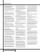
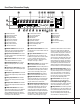
Front Panel Controls 29 30 ı ˆ Ù Û ÚÒ Ô Ó ( * & 1 2 3 4 5 6 7 8 9 ) ! @ $ # % ^ 1 Main Power Switch 2 System Power Control 3 Power Indicator 4 Headphone Jack 5 Selector Buttons 6 Tone Mode 7 Surround Mode Selector 8 Tuning Selector 9 Tuner Band Selector ) Preset Stations Selector ! Input Source Selector @ FM Mode Selector # Digital Optical 3 Input $ Digital Coax 3 Jack % Video 4 Video Input Jacks ^ Video 4 Audio Input Jacks & Bass Control * Balance Control ( Treble Control Ó Volume Con
Front Panel Controls 7 Surround Mode Selector: Press this button to change the surround mode by scrolling through the list of available modes. Note that depending on the type of input, some modes are not always available. (See page 25 for more information about surround modes.) 8 Tuning Selector: Press the left side of the button to tune lower-frequency stations and the right side of the button to tune higher-frequency stations.
Front Panel Information Display A DTS DOLBY D PCM MP3 B W V U X Y AUTO TUNED ST MUTE T SRQ MEMORY PRESET SLEEP P O O L 0 C 0 R O O O OPTICAL 1 2 3 C COAXIAL 1 2 3 DIGITAL PRO LOGIC D E F G ANALOG VMAx NF 5.
Front Panel Information Display T Memory Indicator: This indicator flashes when entering presets and other information into the tuner’s memory. U Stereo Indicator: This indicator lights when an FM station is being tuned in stereo. V Tuned Indicator: This indicator lights when a station is being received with sufficient signal strength to provide acceptable listening quality. W Auto Indicator: This indicator lights when the tuner’s Auto mode is in use.
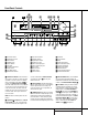
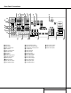
Rear Panel Connections f j 31 L R ¡ d ih g e k L VIDEO R · a A ‰ A ° AC INPUT S-VIDEO ~120V/60HZ A VID 3 IN b c VID 3 1 TAPE ™ OPT OUT IN IN REMOTE 2 £ ANTENNA VID 2 VID 2 OUT OUT MODEL NO.
Rear Panel Connections ¡ Tape Inputs: Connect these jacks to the PLAY/OUT jacks of an audio recorder. ™ Tape Outputs: Connect these jacks to the RECORD/INPUT jacks of an audio recorder. £ Video 1 Audio Inputs: Connect these jacks to the PLAY/OUT audio jacks on a VCR or other video source. ¢ AM Antenna: Connect the AM loop antenna supplied with the receiver to these terminals.
Remote Control Functions 39 POWER d ON OFF MUTE e f DVD VCR TV VID2 VID1 g CD CBL/SAT TAPE VID3 VID4 AM/FM 6 CH. SPL TEST T/V 37 35 SLEEP CH. SURR. VOL. NIGHT SP K q s CH . 30 Y TA L LA DE PR EV 1 2 3 4 5 6 7 8 TUN-M 9 0 MEM 29 28 u v 31 SET IT t 32 o p r 33 ME N E R m 34 U GU ID k n 36 H. i j l 38 .C h AVR EX NOTE: The function names shown here are each button’s feature when used with the AVR 210.
Remote Control Functions IMPORTANT NOTE: The AVR 210’s remote may be programmed to control up to eight devices, including the AVR 210. Before using the remote, it is important to remember to press the Input Selector button e that corresponds to the unit you wish to operate. In addition, the AVR 210’s remote is shipped from the factory to operate the AVR 210 and most Harman Kardon CD or DVD players and cassette decks.
Remote Control Functions will change to monaural reception. (See page 28 for more information.) t Direct Button: Press this button when the tuner is in use to start the sequence for direct entry of a station’s frequency. After pressing the button simply press the proper Numeric Keys r to select a station. (See page 28 for more information on the tuner.) u Tuning Up/Down: When the tuner is in use, these buttons will tune up or down through the selected frequency band.
Installation and Connections System Installation After unpacking the unit, and placing it on a solid surface capable of supporting its weight, you will need to make the connections to your audio and video equipment. Audio Equipment Connections We recommend that you use high-quality interconnect cables when making connections to source equipment and recorders to preserve the integrity of the signals.
Installation and Connections Video Connection Note: • Composite video signals may only be viewed in their native formats. However, S-Video signals will be converted to standard, composite video, and are viewable through the Video Monitor Output ‹. System and Power Connections The AVR 210 is designed for flexible use with multiroom systems, external control components and power amplifiers.
System Configuration Speaker Selection and Placement The placement of speakers in a multichannel home-theater system can have a noticeable impact on the quality of sound reproduced. No matter which type or brand of speakers is used, the same model or brand of speaker should be used for the left front, center and right front speakers.
System Configuration You are now ready to power up the AVR 210 to begin these final adjustments. 1. Plug the Power Cable ° into an unswitched AC outlet. 2. Press the Main Power Switch 1 in until it latches and the word “OFF” on the top of the switch disappears inside the front panel. Note that the Power Indicator 3 will turn amber, indicating that the unit is in the Standby mode. 3. Install the three supplied AAA batteries in the remote as shown.
System Configuration Input Setup The first step in configuring the AVR 210 is to select an input. This may be done by pressing the front panel Input Source Selector ! until the desired input’s name appears momentarily in the Main Information Display X, and the green LED lights next to the input’s name in the front panel Input Indicators . The input may also be selected by pressing the appropriate Input Selector on the remote control eg.
System Configuration To resynchronize the front and surround channels, follow these steps: 1. Measure the distance from the listening position to the front speakers. 2. Measure the distance from the listening position to the surround speakers. 3. Subtract the distance to the surround speakers from the distance to the front speakers. a. When setting the delay time for the Dolby Digital surround modes, the optimal delay time is the result of that subtraction.
System Configuration It is easiest to enter the proper settings for the speaker setup through the SPEAKER SETUP menu (Figure 5). If that menu is not already on your screen from the prior adjustments, press the OSD button v to bring up the MASTER MENU (Figure 1), and then press the ¤ button q twice so that the cursor is on the SPEAKER SETUP line. At this point, press the Set button o to bring up the SPEAKER SETUP menu (Figure 5).
System Configuration Within three seconds, press either the front panel ‹ / › Selector buttons 5 or the ⁄/¤ buttons mq on the remote to select a different speaker position, or press the Set button Ôo to begin the adjustment process for the front left and right speakers. When the Set button Ôo has been pressed and the system is ready for a change to the speaker setting, the on-screen display and Main Information Display X will read FNT LARGE or FNT SMALL, depending on the current setting.
System Configuration the level. This is a normal aspect of the system’s operation. • As the other channels are set, the channel name and the adjustment offset will appear in the on-screen display (if connected) and the Main Information Display X. While the level is changing, the Program/SPL Indicator c will change colors to reflect the output level in relation to the reference. A red indication shows that the level is too high, while an amber indication shows that the level is too low.
System Configuration Additional Input Adjustments After one input has been adjusted for surround mode, digital input (if any), speaker type, and output levels, go back to the INPUT SETUP line on the MASTER MENU and enter the settings for each input that you will use.
Operation Basic Operation Once you have completed the setup and configuration of the AVR 210, it is simple to operate and enjoy. The following instructions will help you maximize the enjoyment of your new receiver: Turning the AVR 210 On or Off • When using the AVR 210 for the first time, you must press the Main Power Switch 1 on the front panel to turn the unit on. This places the unit in a Standby mode, as indicated by the amber color of the Power Indicator 3 .
Operation Surround Mode Chart MODE FEATURES DELAY TIME RANGE DOLBY DIGITAL Available only with digital input sources encoded with Dolby Digital data. It provides up to five separate main audio channels and a special dedicated Low-Frequency Effects channel. Center: 0 ms – 5 ms Initial Setting – 0 ms Surround: 0 ms – 15 ms Initial Setting – 0 ms DTS Available only with digital input sources encoded with DTS data.
Operation Surround Mode Selection One of the most important features of the AVR 210 is its ability to reproduce a full multichannel surround-sound field from digital sources, analog matrix surround-encoded programs and standard stereo programs. In all, a total of twelve listening modes are available on the AVR 210. Selection of a surround mode is based on personal taste, as well as the type of program source material being used.
Operation playing, the AVR 210 will automatically detect whether it is a multichannel Dolby Digital, DTS source, MP3 or a conventional PCM signal, which is the standard output from CD players. A Bitstream Indicator A will light in the Main Information Display Û to confirm that the digital signal is Dolby Digital, DTS or PCM. MP3: When the MP3 indicator lights, a compatible MPEG 1/Layer 3 digital signal is being received.
Operation that some future digital sources may not be compatible with the AVR 210. 3. Note that not all digitally encoded programs contain full 5.1-channel audio. Consult the program guide that accompanies the DVD or laser disc to determine which type of audio has been recorded on the disc. The AVR 210 will automatically sense the type of digital surround encoding used and adjust to accommodate it. 4.
Operation 1. Press the Memory button 29 on the remote. Note that the MEMORY indicator T will be illuminated and flash in the Main Information Display Û. 2. Within five seconds, press the Numeric Keys r corresponding to the location where you wish to store this station’s frequency. Once entered, the preset number will appear in the Preset Number/Sleep Time Display Q. 3. Repeat the process after tuning any additional stations to be preset.
Operation 6-Channel Direct Input The AVR 210 is equipped for future expansion through the use of optional, external adapters for formats that the AVR 210 may not be capable of processing. When an adapter is connected to the 6-Channel Direct Input ª, you may select it by pressing the 6-Ch Direct Input Selector 37 .
Advanced Features The AVR 210 is equipped with a number of advanced features that add extra flexibility to the unit’s operation. While it is not necessary to use these features to operate the unit, they provide additional options that you may wish to use. Display Brightness The AVR 210’s Main Information Display Û is set at a default brightness level that is sufficient for viewing in a normally lit room.
Advanced Features activated, even if they were switched off for the previous listening session. To change the length of time that the semi-OSD displays remain on the screen, go to the ADVANCED SELECT menu as outlined earlier, and press the ⁄/¤ buttons mq as needed, until the on-screen › cursor is next to the SEMI-OSD TIME OUT line. Next, press the ‹ / › buttons n 31 until the desired time in seconds is displayed.
Programming the Remote The AVR 210 is equipped with a powerful remote control that will control not only the receiver’s functions, but also most popular brands of audio and video equipment, including CD players, cassette decks, TV sets, cable boxes, VCRs, satellite receivers and other home-theater equipment.
Programming the Remote Macro Programming Macros enable you to easily repeat frequently used combinations of commands with the press of a single button on the AVR 210’s remote control. Once programmed, a macro will send out up to 19 different remote codes in a predetermined sequential order, enabling you to automate the process of turning on your system, changing devices, or other common tasks.
Programming the Remote buttons when operating most TV sets, VCRs or cable boxes. The Channel Up/Down indication is printed directly on the remote. For many standard CD players, cassette decks, VCRs and DVD functions, the standard function icons are printed on top of the buttons. For some products, however, the function of a particular button does not follow the command printed on the remote. In order to see which function a button controls, consult the Function List tables printed on pages 37 and 38.
Programming the Remote the Input Selector e and the Program/ SPL Indicator c flashes amber. 2. Press the Play button x. The Program/SPL Indicator c will stop flashing and stay amber. 3. Press and release the Input Selector button e for the device that will be used to change the channels. The Program/SPL Indicator c will blink green three times and then go out to confirm the data entry.
Function List No.
Function List (continued) No. Button Name AVR Function DVD 45 Direct Direct Tuner Entry 46 Clear Clear Clear 47 Preset Up Preset Tune Up Slow Forward 48 Tune Down Tune Down Prev Chapter 49 OSD OSD 50 D.
Setup Code Table: TV Manufacturer/Brand Setup Code Number A MARK ADMIRAL AKAI AMPRO AMSTRAD ANAM AOC BELL & HOWELL BROKSONIC CANDLE CAPEHART CENTURION CENTRONIC CITIZEN CLASSIC CONCERTO CONTEC CORANDO CRAIG CROWN CURTIS MATHES DAEWOO DAYTRON DYNASTY DYNATECH ELECTROHOME EMERSON ENVISION FISHER FUNAI FUTURETECH GE GOLDSTAR GRUNDIG HALL MARK HARMAN KARDON HITACHI INFINITY INKEL JBL JC PENNEY JENSEN JVC KEC KENWOOD KLOSS KTV LUXMAN LXI MAGNAVOX MAJESTIC 097 069 001 070 053 045 001 069 091 001 059 170 045 00
Setup Code Table: TV (continued) MARANTZ MEMOREX MGA MIDLAND MITSUBISHI NAD NATIONAL NEC OPTIMUS OPTONICA ORION PANASONIC PENNEY PHILCO PHILIPS PIONEER PORTLAND PROSCAN PROTON QUASAR RADIO SHACK RCA REALISTIC RUNCO SAMPO SAMSUNG SANSUI SANYO SCOTT SEARS SHARP SIGNATURE SONY SOUNDESIGN SSS SUPRE MACY SYLVANIA SYMPHONIC TANDY TATUNG TECHNICS TECHWOOD TEKNIKA TELEFUNKEN TELERENT TMK TOSHIBA UNIVERSAL VIDEO CONCEPTS VIDTECH WARDS YAMAHA ZENITH 001 011 001 199 001 021 177 001 031 025 091 039 199 001 001 001 011
Setup Code Table: VCR Manufacturer/Brand Setup Code Number AIWA AKAI AMPRO AMSTRAD ANAM AUDIO DYNAMICS BROKSONIC CANDLE CANON CAPEHART CITIZEN CRAIG CURTIS MATHES DAEWOO DAYTRON DBX DUAL ELECTROHOME EMERSON FISHER FUNAI GE GO VIDEO GOLDSTAR GRAETZ HARMAN KARDON HITACHI INSTANTREPLAY JC PENNEY JENSEN JVC KENWOOD LLOYD LXI MAGNAVOX MARANTZ MARTA MEMOREX MGA MINOLTA MITSUBISHI MULTITECH NAD NATIONAL NEC NORDMENDE OPTIMUS OPTONICA ORION PANASONIC PENTAX 040 022 076 133 037 018 031 134 034 094 021 003 037 012
Setup Code Table: VCR (continued) PHILCO PHILIPS PILOT PIONEER PORTLAND PULSAR QUARTZ QUASAR RADIO SHACK RCA REALISTIC RICO SAMSUNG SANSUI SANYO SCOTT SEARS SHARP SHINTOM SONY SOUNDESIGN STS SYLVANIA SYMPHONIC TANDY TATUNG TEAC TECHNICS TEKNIKA TMK TOSHIBA TOTEVISION UNITECH VECTOR RESEARCH VICTOR VIDEO CONCEPTS VIDEOSONIC WARDS YAMAHA ZENITH 037 037 087 019 094 076 002 039 003 019 003 028 038 028 003 023 003 037 030 003 040 019 037 040 040 044 040 037 025 013 015 045 045 018 052 018 045 003 018 040 039 0
Setup Code Table: CD Manufacturer/Brand Setup Code Number ADC ADCOM AIWA AKAI AUDIO TECHNICA AUDIOACCESS BSR CALIFORNIA AUDIO CAPETRONIC CARRERA CARVER CASIO CROWN CURTIS MATHES DENON EMERSON FISHER FUNAI GE GOLDSTAR HAITAI HARMAN KARDON HITACHI INKEL JC PENNEY JENSEN JVC KENWOOD KYOCERA LOTTE LUXMAN LXI MAGNAVOX MARANTZ MACINTOSH MEMOREX MGA MISSION MITSUBISHI MITSUMI NAD NAKAMICHI NEC NIKKO NSM ONKYO OPTIMUS PANASONIC PHILIPS PIONEER PROTON 010 047 079 048 051 123 042 013 068 062 049 064 040 064 007 04
Setup Code Table: CD (continued) QUASAR RADIO SHACK RCA REALISTIC ROTEL SAE SAMSUNG SANSUI SANYO SCOTT SEARS SHARP SHERWOOD SIGNATURE SONY SOUNDSTREAM STS SYLVANIA SYMPHONIC TANDY TEAC TECHNICS THETA DIGITAL TOSHIBA VECTOR RESEARCH VICTOR WARDS YAMAHA YORK 013 120 022 047 049 049 026 045 031 106 064 018 008 038 005 122 010 049 057 094 009 013 037 011 085 027 038 017 120 44 SETUP CODES 107 124 047 054 079 055 091 148 056 091 093 049 055 079 066 132 155 080 093 170 166 056 024 071 025 103 112 039
Setup Code Table: DVD Manufacturer/Brand CALIFORNIA AUDIO DENON GE GOLDSTAR HARMAN KARDON JVC KENWOOD LOTTE MAGNAVOX MITSUBISHI NAD ONKYO OPTIMUS PANASONIC PIONEER RCA RUNCO SAMSUNG SANYO SHARP SONY TECHNICS THOMSON TOSHIBA YAMAHA Setup Code Number 032 002 019 022 003 004 005 001 006 007 008 009 023 036 010 015 011 024 012 020 035 018 027 031 013 021 028 037 014 029 034 026 003 004 033 016 017 030 45 SETUP CODES
Setup Code Table: SAT Manufacturer/Brand Setup Code Number ALPHASTAR ALPHASTAR DBS ALPHASTAR DSR CHANNEL MASTER CHAPARRAL CITOH DRAKE DX ANTENNA ECHOSTAR ELECTRO HOME EUROPLUS FUJITSU GENERAL ELECTRIC GENERAL INSTRUMENT HITACHI HITACHI DBS HOUSTON TRACKER HUGHES JANIEL JERROLD JERROLD PRIMASTER KATHREIN LEGEND LUXOR MACOM MAGNAVOX MEMOREX NEXTWAVE NORSAT OPTIMUS PANASONIC PANASONIC DBS PANSAT PERSONAL CABLE PHILIPS PICO PRESIDENT PRIMESTAR RCA RCA DBS REALISTIC SAMSUNG SATELLITE SERVICE CO SCIENTIFIC ATLA
Setup Code Table: CBL Manufacturer/Brand Setup Code Number ABC ALLEGRO AMERICAST ANTRONIX ARCHER BELCOR CABLE STAR CENTURION CENTURY CITIZEN COMTRONICS DIAMOND DIGI EAGLE EASTERN ELECTRICORD EMERSON FOCUS G.I.
Setup Code Table: CBL (continued) REGENCY REMBRANT SAMSUNG SCIENTIFIC ATLANTA SIGNAL SIGNATURE SPRUCER STARCOM STARGATE SYLVANIA TANDY TELECAPATION TEXSCAN TFC TIMELESS TOCOM TOSHIBA UNIKA UNITED CABLE UNIVERSAL VIDEOWAY VIEWSTAR ZENITH ZENTEK 063 032 037 003 037 001 053 002 015 071 024 028 036 122 123 045 058 014 059 012 124 019 058 116 115 187 072 186 018 047 048 052 130 145 183 203 204 188 081 177 189 015 016 141 163 037 120 187 071 046 062 170 205 021 031 014 021 031 033 034 039 042 113 211 022 025
Troubleshooting Guide SYMPTOM CAUSE SOLUTION Unit does not function when Main Power Switch is pushed • No AC Power • Make certain AC power cord is plugged into a live outlet • Check to see whether outlet is switch-controlled Display lights, but no sound or picture • Intermittent input connections • Mute is on • Volume control is down • Make certain that all input and speaker connections are secure • Press Mute button • Turn up volume control Unit turns on, but front panel display does not light up
Technical Specifications Audio Section Stereo Mode Continuous Average Power (FTC) 50 Watts per channel, 20Hz–20kHz, @ < 0.07% THD, both channels driven into 8 ohms Five-Channel Surround Modes Power Per Individual Channel Front L&R channels: 40 Watts per channel @ < 0.07% THD, 20Hz–20kHz into 8 ohms Center channel: 40 Watts @ < 0.07% THD, 20Hz–20kHz into 8 ohms Surround channels: 40 Watts per channel @ < 0.
Notes 51 NOTES
250 Crossways Park Drive, Woodbury, New York 11797 www.harmankardon.com © 2000 Harman Kardon, Incorporated Part No.