AVR7300(120v)-OM 6/14/04 9:15 AM Page 1 ® ® Power for the Digital Revolution.
AVR7300(120v)-OM 6/14/04 9:15 AM Page 2 AVR 7300 AUDIO/VIDEO RECEIVER 3 4 4 5 9 11 13 17 18 21 21 21 23 24 24 26 28 29 30 31 32 34 34 34 35 35 35 35 36 39 40 40 40 42 42 42 42 42 43 44 44 44 45 46 46 47 48 49 51 52 53 54 56 57 59 Introduction Important Safety Information Unpacking Front-Panel Controls Rear-Panel Audio Connections Video and System Connections Main Remote Control Functions Zone II Remote Control Functions Installation and Connections System Configuration Speaker Placement System Setup In
AVR7300(120v)-OM 6/14/04 9:15 AM Page 3 INTRODUCTION Thank You for Choosing Harman Kardon® Packed with state-of-the-art features to bring out the best in any audio or video program, the AVR 7300 will be the centerpiece of your home entertainment system for years to come. Thanks to sophisticated technology, the AVR 7300 is able to accommodate virtually any combination of program sources, speakers and room sizes, yet it is easy to set up and operate.
AVR7300(120v)-OM 6/14/04 9:15 AM Page 4 SAFETY INFORMATION Important Safety Information Verify Line Voltage Before Use Your AVR 7300 has been designed for use with 120-volt AC current. Connection to a line voltage other than that for which it is intended can create a safety and fire hazard and may damage the unit.
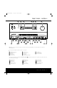
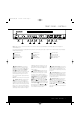
AVR7300(120v)-OM 6/14/04 9:15 AM Page 5 FRONT-PANEL CONTROLS % ^ 1 2 6 4 1 7 5 3 # @ $ 9 10 6 ) 14 12 11 8 45 2 3 ! 13 15 7 8 9 NOTE: To make it easier to follow the instructions that refer to this illustration, a larger copy may be downloaded from the Product Support section for this product at www.harmankardon.com.
AVR7300(120v)-OM 6/14/04 9:15 AM Page 6 FRONT-PANEL CONTROLS 1 Standby/On Button: When the Main Power Switch 1 is pressed in so that it is in the “ON” position, press this button to turn on the AVR 7300. When the unit is in the Standby mode, the switch is surrounded by amber lighting. When the unit is on, the lighting around the button is blue. 2 Surround Mode Group Selector: Press this button to select the top-level group of surround modes.
AVR7300(120v)-OM 6/14/04 9:15 AM Page 7 FRONT-PANEL CONTROLS 1 2 4 9 7 5 3 6 8 13 11 10 12 15 14 NOTE: To make it easier to follow the instructions that refer to this illustration, a larger copy may be downloaded from the Product Support section for this product at www.harmankardon.com. The following controls and jacks are located behind the front-panel door. To open the door, place the edge of a finger on the left or right bottom edge of the panel and gently swing the door down toward you.
AVR7300(120v)-OM 6/14/04 9:15 AM Page 8 FRONT-PANEL CONTROLS 7 Delay Adjust Selector: Press this button to begin the process of adjusting the delay settings. See page 28 for more information on delay adjustments. 12 Coaxial 4 Digital Input: Connect the coaxial digital output of a digital audio product such as a portable audio player or video game to this jack.
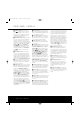
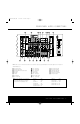
AVR7300(120v)-OM 6/14/04 9:15 AM Page 9 REAR-PANEL AUDIO CONNECTIONS √ ∂ ∫ å ç †ß ® ü ƒ é ∆ ˙ © î œ πå ñ ç ¬ ˚ ∫ µ ø NOTE: To make it easier to follow the instructions that refer to this illustration, a larger copy may be downloaded from the Product Support section for this product at www.harmankardon.com.
AVR7300(120v)-OM 6/14/04 9:15 AM Page 10 REAR-PANEL AUDIO CONNECTIONS å Front Speaker Outputs: Connect these outputs to the matching + or – terminals on your left and right speakers. When making speaker connections, always make certain to maintain correct polarity by connecting the color-coded (white for front left and red for front right) (+) terminals on the AVR 7300 to the red (+) terminals on the speakers and the black (–) terminals on the AVR 7300 to the black (–) terminals on the speakers.
AVR7300(120v)-OM 6/14/04 9:15 AM Page 11 VIDEO AND SYSTEM CONNECTIONS X V W A C B E D F U H J S O M I K G R T L N Q P NOTE: To make it easier to follow the instructions that refer to this illustration, a larger copy may be downloaded from the Product Support section for this product at www.harmankardon.com.
AVR7300(120v)-OM 6/14/04 9:15 AM Page 12 VIDEO AND SYSTEM CONNECTIONS A Amp Trigger: Connect this jack to the “Trigger In” jack of an optional, external power amplifier that is equipped for remote turn-on via a 6-volt signal. When this connection is used, the AVR 7300 will automatically send a low-voltage signal that turns on the amp when the AVR is on, and since the signal is not present when the AVR is turned off, the amplifier will also turn off with the AVR 7300.
AVR7300(120v)-OM 6/14/04 9:15 AM Page 13 MAIN REMOTE CONTROL FUNCTIONS 0 Power Off Button 1 Power On Button 2 LCD Information Display 3 Input Selectors 4 AVR Selector 5 DSP Surround Mode Selector 6 Test Button 7 Video Processing On/Off Button 8 Direct Button 9 Clear Button A Numeric Keys B Tuning Mode Button m Dim Button n Channel Select Button o Navigation Button F Digital Select Button G Set Button H Volume Up/Down Buttons I Transport Fast-Play/Scan Buttons J Main Transport Controls K Track Skip Up/Do
AVR7300(120v)-OM 6/14/04 9:15 AM Page 14 MAIN REMOTE CONTROL FUNCTIONS IMPORTANT NOTE: The AVR 7300’s remote may be programmed to control up to nine devices, including the AVR 7300. Before using the remote, it is important to remember to press the Input Selector Button 3 that corresponds to the unit you wish to operate. In addition, the AVR 7300’s remote is shipped from the factory to operate the AVR 7300 and most Harman Kardon CD or DVD players and cassette decks.
AVR7300(120v)-OM 6/14/04 9:15 AM Page 15 MAIN REMOTE CONTROL FUNCTIONS s Transport Fast-Play/Scan Buttons: These buttons have no direct function on the AVR 7300, but they are used when the remote is programmed for a compatible DVD, CD or tape player. Pressing these buttons will transmit a fast-play forward, fast-play reverse, or fast-forward or fast-reverse scan command, according to the capabilities of the player being controlled.
AVR7300(120v)-OM 6/14/04 9:15 AM Page 16 MAIN REMOTE CONTROL FUNCTIONS Delay Select Button: This button selects adjustments to the A/V Sync Delay and the individual channel delays. The first press of the button displays an A/V SYNC DELAY message in the Lower Display Line $ and in the on-screen display, which means that you may change the amount of time that all channels are delayed together behind the video.
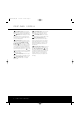
AVR7300(120v)-OM 6/14/04 9:15 AM Page 17 ZONE II REMOTE CONTROL FUNCTIONS POWER A MUTE K OFF AVR VID1 VID2 AM//FM VID3 VID4 DVD CD TAPE DN TUNING UP DN PRESET UP B C D E F G H DISC SKIP J DISC SKIP I VOLUME The Zone II remote may be used either in the same room where the AVR 7300 is located or in a separate room with an optional infrared sensor that is connected to the AVR 7300’s Multiroom IR Input B jack.
AVR7300(120v)-OM 6/14/04 9:15 AM Page 18 INSTALLATION AND CONNECTIONS System Installation After unpacking the unit, locating it in a place with adequate ventilation and placing it on a solid surface capable of supporting its weight, you will need to make the connections to your audio and video equipment.
AVR7300(120v)-OM 6/14/04 9:15 AM Page 19 INSTALLATION AND CONNECTIONS on page 48. You may also “learn” the codes for most remotes to any input button on the remote by following the instructions for “Learning Commands” as shown on page 47. 4. Connect the analog left/right audio and composite video or S-Video and analog left/right audio outputs of a DVD player to the DVD Audio and Video Input Jacks ©I on the rear panel. 5.
AVR7300(120v)-OM 6/14/04 9:15 AM Page 20 INSTALLATION AND CONNECTIONS use the full 7.1-channel capabilities of the AVR 7300 in the main listening room, but you will be able to add another listening room without external power amplifiers. To use the internal amplifiers to power a remote zone, connect the speakers for the remote room location to the Surround Back/Multiroom Speaker Outputs ç.
AVR7300(120v)-OM 6/14/04 9:15 AM Page 21 SYSTEM CONFIGURATION When all audio, video and system connections have been made, there are a few configuration adjustments that must be made. A few minutes spent to correctly configure and calibrate the unit will greatly add to your listening experience.
AVR7300(120v)-OM 6/14/04 9:15 AM Page 22 SYSTEM CONFIGURATION 4. Install the four supplied AAA batteries in the remote as shown. Be certain to follow the (+) and (–) polarity indicators that are in the battery compartment. Making Configuration Adjustments The full-OSD system is available by pressing the OSD Button . When this button is pressed, the MASTER MENU (Figure 1) will appear, and adjustments are made from the individual menus.
AVR7300(120v)-OM 6/14/04 9:15 AM Page 23 SYSTEM CONFIGURATION Input Setup The first step is to configure each input. Once an input is selected, the settings mode will “attach” themselves to that input and be stored in a nonvolatile memory. This means that once configured, the selection of an input will automatically recall those settings.
AVR7300(120v)-OM 6/14/04 9:15 AM Page 24 SYSTEM CONFIGURATION In cases in which you wish to have the output of a digital source selected as the record output feed, while the ➔ cursor is next to the REC OUT line, press the ‹/› Navigation Button o so that DSP DOWNMIX appears.
AVR7300(120v)-OM 6/14/04 9:15 AM Page 25 SYSTEM CONFIGURATION When Dolby Pro Logic II Music or Dolby Pro Logic IIx Music is selected as the listening mode, three special settings are available to tailor the sound field to your listening room environment and your individual taste and preferences. (When other Dolby Surround modes are selected, dotted lines will indicate that these settings are not active.
AVR7300(120v)-OM 6/14/04 9:15 AM Page 26 SYSTEM CONFIGURATION are processed at their native sample rate. For example, a 48kHz digital source will be processed at 48kHz. However, the AVR 7300 allows you to upsample the incoming 48kHz signals to 96kHz for added resolution. To take advantage of this feature, press the ⁄/¤ Navigation Button o so that the ➔ cursor is next to the UPSAMPLING line and press the ‹/› Navigation Button o so that ON is highlighted in reverse video.
AVR7300(120v)-OM 6/14/04 9:15 AM Page 27 SYSTEM CONFIGURATION When NONE is selected, the system will adjust so that only 5.1-channel modes are available. When this is the case for your system, you may wish to use the surround back amplifier channels to power a second set of speakers whose source is selected by the AVR 7300’s multiroom system. See page 39. When SMALL is selected, the system will adjust so that the full complement of 6.1/7.
AVR7300(120v)-OM 6/14/04 9:15 AM Page 28 SYSTEM CONFIGURATION speaker configuration and crossover settings. NOTE: The independent feature allows you to select a different speaker size configuration (Large, Small or None, as appropriate) for each input source.
AVR7300(120v)-OM 6/14/04 9:15 AM Page 29 SYSTEM CONFIGURATION Output Level Adjustment Output level adjustment is a key part of the configuration of any surround sound product. It is particularly important for a digital receiver such as the AVR 7300, as correct outputs ensure that you hear soundtracks with the proper directionality and intensity. IMPORTANT NOTE: Listeners are often confused about the operation of the surround channels.
AVR7300(120v)-OM 6/14/04 9:15 AM Page 30 SYSTEM CONFIGURATION press the ¤ Navigation Button o to bring the CHANNEL ADJUST menu (Figure 13) to the screen. When the CHANNEL ADJUST menu first appears, the test tone is off. Use the ⁄/¤ Navigation Button o to select any channel for adjustment using an external source, such as a test disc, from which to judge the output levels. After the ➔ cursor is pointing to the channel to be adjusted, press the ‹/› Navigation Button o to raise or lower the output level.
AVR7300(120v)-OM 6/14/04 9:15 AM Page 31 SYSTEM CONFIGURATION * T O N E → T O N E B A S S T R E B L E B A C K T O C O N T R O L * : I N : 0 : 0 A U D I O S E T U P Figure 15 The first line controls whether the bass/treble tone controls are in the signal path.
AVR7300(120v)-OM 6/14/04 9:15 AM Page 32 SYSTEM CONFIGURATION analog channels. We recommend that you start with this setting and then change the options in the ADVANCED CONFIGURATION menus as needed to tailor the output to your preferences. SAT DIG: This setting is optimized for use with digital satellite-system set-top boxes. CABLE ANALOG: This setting is optimized for use with analog cable set-top boxes. SAT ANALOG: This setting is optimized for use with analog satellite-system set-top boxes.
AVR7300(120v)-OM 6/14/04 9:15 AM Page 33 SYSTEM CONFIGURATION * → N X D F F F C A O C I I L O D I C D L L E M TO V S O i M M S P ANC E R LOR IN MO MO HTO VI ED EDU SU TER DE DE NE DEO VIDEO C C P P D E N O T P O E D O E N I R L T I I N MAIN F O E A E T S H I N S T C G S I T D R AN O O E E C PAG : R : N : : T : D : E : E O O O O O O O 1 * N N N N N N N PAGE1 Figure 17 The settings available on Page 1 of the ADVANCED CONFIGURATION menu are the following: NOISE REDUCTION: When this set
AVR7300(120v)-OM 6/14/04 9:15 AM Page 34 OPERATION Basic Operation Once you have completed the initial setup and configuration of the AVR 7300, it is simple to operate and enjoy. The following instructions will help you maximize the enjoyment of your new receiver: Turning the AVR 7300 On or Off • When using the AVR 7300 for the first time, you must press the Main Power Button 1 to turn the unit on.
AVR7300(120v)-OM 6/14/04 9:15 AM Page 35 OPERATION Volume and Tone Control Video Processing • Adjust the volume to a comfortable level using the front-panel Volume Control ) or remote Volume Up/Down Buttons r . The AVR 7300 features unique combination of video scaling and processing options that are available when the unit is connected to a “digital ready” or HD capable display device.
AVR7300(120v)-OM 6/14/04 9:15 AM Page 36 OPERATION Surround Mode Chart MODE FEATURES Dolby Digital Available only with digital input sources encoded with Dolby Digital data. It provides up to five separate main audio channels and a special dedicated low-frequency effects channel. Dolby Digital EX Available when the receiver is configured for 6.1/7.1 channel operation, Dolby Digital EX is the latest version of Dolby Digital.
AVR7300(120v)-OM 6/14/04 9:15 AM Page 37 OPERATION dynamic range and significant improvements to signalto-noise ratios. In addition, digital systems have the capability to deliver an additional channel that is specifically devoted to low-frequency information. This is the “.1” channel referred to when you see these systems described as “5.1,” “6.1” or “7.1.
AVR7300(120v)-OM 6/14/04 9:15 AM Page 38 OPERATION When Dolby Digital 3/2/.1 or DTS or DTS-ES signals are being played, the DPR will automatically switch to the proper surround mode, and no other processing may be selected. When a Dolby Digital signal with a 3/1/0 or 2/0/0 signal is detected, you may select any of the Dolby surround modes. When DS-OFF appears as a message, it indicates that there is no Dolby Surround data flag in the audio bitstream.
AVR7300(120v)-OM 6/14/04 9:15 AM Page 39 OPERATION MP3 Audio Playback The AVR 7300 is one of the few receivers equipped for onboard decoding for the MP3 audio format used by computers and portable audio devices.
AVR7300(120v)-OM 6/14/04 9:15 AM Page 40 OPERATION To enter a station into the memory, first tune the station using the steps outlined above. Then: 1. Press the Memory Button 39 on the remote; the station’s frequency will flash. 2. Within five seconds, press the Numeric Keys k corresponding to the memory location where you wish to store this station’s frequency. Once entered, the preset number will appear in the Upper Display Line #. 3.
AVR7300(120v)-OM 6/14/04 9:15 AM Page 41 OPERATION make other adjustments. If you have no other adjustments to make, press the OSD Button to exit the menu system. NOTE: Output levels may be separately trimmed for each surround mode. If you wish to have different trim levels for a specific mode, select that mode and then follow the instructions shown above.
AVR7300(120v)-OM 6/14/04 9:15 AM Page 42 ADVANCED FEATURES The AVR 7300 is equipped with a number of advanced features that add extra flexibility to the unit’s operation. While it is not necessary to use these features to operate the unit, they provide additional options that you may wish to use. Front-Panel Display Fade In normal operation, the front-panel displays and indicators remain on at full brightness, although you may also dim them or turn them off as shown on page 41.
AVR7300(120v)-OM 6/14/04 9:15 AM Page 43 ADVANCED FEATURES To adjust the on-screen appearance of the semi-OSD system, press the OSD Button to bring the MASTER MENU to the screen. Press the ¤ Navigation Button o, until the on-screen ➔ cursor is next to the ADVANCED line. Press the Set Button q to enter the ADVANCED SELECT menu (Figure 19). When the ADVANCED SELECT menu (Figure 19) appears, press the ⁄/¤ Navigation Button o so that the on-screen ➔ cursor is pointing to the SEMI OSD/TIME OUT line.
AVR7300(120v)-OM 6/14/04 9:15 AM Page 44 MULTIROOM OPERATION The AVR 7300 is fully equipped to operate as the control center for a complete multiroom system that is capable of sending one audio/video source to a second zone in the house while a separate source is listened to in the main room. In addition to providing for control over the selection of the remote source and its volume, the AVR 7300 offers a comprehensive range of options for powering the speakers in the second zone.
AVR7300(120v)-OM 6/14/04 9:15 AM Page 45 MULTIROOM OPERATION Once this setting is made, you may press the ⁄/¤ Navigation Button o to make any of the other adjustments available on this menu. If no other adjustments are needed, press the OSD Button to exit the menu system.
AVR7300(120v)-OM 6/14/04 9:15 AM Page 46 CONFIGURING THE REMOTE The AVR 7300 remote is factory-programmed for all functions needed to operate the unit. In addition, it is also preprogrammed to operate most recent Harman Kardon DVD players and changers, CD players and changers, CD recorders and cassette decks. The codes for other brand devices may be programmed into the AVR 7300 remote using its extensive library of remote codes or a head-to-head learning process for codes not in the internal library.
AVR7300(120v)-OM 6/14/04 9:15 AM Page 47 CONFIGURING THE REMOTE that does not operate properly by using the learning technique shown on this page. Automatic Code Entry In addition to manual code selection using the brand name list, it is also possible to automatically search through all the codes that are stored in the AVR remote’s library to see whether a device will respond even if it is not listed among the brands that appear when you program the remote manually.
AVR7300(120v)-OM 6/14/04 9:15 AM Page 48 CONFIGURING THE REMOTE commands from another device’s remote into the AVR remote. MAIN MENU LEARN Figure 32 3. The SELECT A DEVICE message will appear in the LCD display (Figure 23). Press the ⁄ / ¤ Navigation Buttons o to scroll through the list of device categories and press the Set Button q when the device for which you wish to set the codes appears. For this example, we will select “TV” to enter the codes needed to operate your TV. 4.
AVR7300(120v)-OM 6/14/04 9:15 AM Page 49 CONFIGURING THE REMOTE “TV,” and show how to change it to take on the codes for operating a VCR. When that device’s name appears, press the Set Button q. OLD DEVICE TYPE TV Figure 41 4. Once the “old” device type has been selected, you need to tell the remote which set of remote codes to use as a replacement for the device just selected.
AVR7300(120v)-OM 6/14/04 9:15 AM Page 50 CONFIGURING THE REMOTE you must first press the Input Selectors d for that button, and then press the Command or Function key. Since we want to program a series of events that occur each time the Power On button is pressed, press the AVR button. In your specific macro, this is the first command button. SELECT A DEVICE AVR Figure 47 7. The next display (Figure 48) and the subsequent screens are where the actual macro programming takes place.
AVR7300(120v)-OM 6/14/04 9:16 AM Page 51 CONFIGURING THE REMOTE next to the bracketed read-out of the underlying device (e.g., [AVR] POWER ON). 6. When you are finished reviewing the macro’s contents, press the Set Button q to return the remote to normal operation.
AVR7300(120v)-OM 6/14/04 9:16 AM Page 52 CONFIGURING THE REMOTE Button o until the desired device name appears to the right of the device in use. In our example, that is the cable box. When the desired combination of devices appears, press the Set Button q. PUNCH-THROUGH VCR<-CBL Figure 62 6. When the Set button is pressed, the display will change to show you that the new combination of control commands is being saved to the unit’s memory, as shown in Figure 63.
AVR7300(120v)-OM 6/14/04 9:16 AM Page 53 CONFIGURING THE REMOTE 3. At the next menu screen (Figure 71) press the ⁄ / ¤ Navigation Buttons o once so that EZSET DISABLE appears in the lower line of the LCD display. SET SPKR LEVELS E ZS ET D I S A B L E Figure 71 4. Within five seconds, press the Set Button q to disable the SPL Select Button . Once the Set Button q is pressed, the word EXITING will flash four times in the lower line of the LCD display and then it will return to normal operation.
AVR7300(120v)-OM 6/14/04 9:16 AM Page 54 CONFIGURING THE REMOTE Renaming Individual Keys Thanks to the programming flexibility of the AVR remote, an individual button on the remote may be assigned a feature or function that is different from the name that appears as the factory default when the button is pressed. However, with the Rename Key function it is possible to rename almost any button on the remote so that when the button is pressed you will see a more descriptive or appropriate name displayed.
AVR7300(120v)-OM 6/14/04 9:16 AM Page 55 CONFIGURING THE REMOTE any settings you had previously made will have to be reentered. To erase all settings and reset the remote to the original factory default settings and displays, follow these steps: 1. Press and hold the Program Button O for about three seconds while the message shown in Figure 21 appears in the remote’s LCD Information Display 2. Release the button when the red light under the Set Button q appears. 2.
AVR7300(120v)-OM 6/14/04 9:16 AM Page 56 TROUBLESHOOTING GUIDE SYMPTOM CAUSE SOLUTION Unit does not function when Main Power Switch is pushed • No AC Power • Make certain that the AC power cord is plugged into a live outlet • Check to see whether the outlet is switch-controlled Display lights, but no sound or picture • Intermittent input connections • Mute is on • Volume control is down • Make certain that all input and speaker connections are secure • Press Mute Button 33 • Turn up the volume c
AVR7300(120v)-OM 6/14/04 9:16 AM Page 57 APPENDIX SYSTEM DEFAULTS The three tables in this section show the factory default settings for the Video Inputs, Video Sources and Video Display Aspect Ratios. These tables give you the complete picture on the AVR 7300’s initial settings. You may then decide whether any item needs to be changed so that it is more appropriate for your specific installation.
APPENDIX Saturation Contrast Brightness Output Aspect Ratio VCR Sync Time Enhancement Composite Video Enhancement Fleshtone Noise Reduction Film Mode Edit Detect Film Mode Detect DCDi Interpolation X-Color Suppressor Noise Reduction Input Aspect Ratio Enhance Level Video Input Port Video Source Type Auto Poll Digital Audio Input Component Video Input Surround Back X-Over Surround L/R X-Over Front L/R X-Over Subwoofer VIDEO 1 VIDEO 2 VIDEO 3 VIDEO 4 VIDEO 5 CD TAPE 6/8 CH D
AVR7300(120v)-OM 6/14/04 9:16 AM Page 59 AVR 7300 TECHNICAL SPECIFICATIONS Audio Section Stereo Mode Continuous Average Power (FTC) 125 Watts per channel, 20Hz–20kHz, @ <0.07% THD, both channels driven into 8 ohms Seven-Channel Surround Modes Power per Individual Channel Front L&R channels: 110 Watts per channel @ <0.07% THD, 20Hz–20kHz into 8 ohms Center channel: 110 Watts @ <0.07% THD, 20Hz–20kHz into 8 ohms Surround (L & R Side, L & R back) channels: 110 Watts per channel @ <0.
AVR7300(120v)-OM 6/14/04 9:16 AM Page 60 250 Crossways Park Drive, Woodbury, New York 11797 www.harmankardon.com © 2004 Harman International Industries, Incorporated Part No.