250 Crossways Park Drive, Woodbury, New York 11797 www.harmankardon.
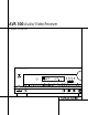
AVR 500 Audio/Video Receiver OWNER’S MANUAL AVR 500 Volum Speaker Multi Room Dig. Select Delay COAX DIGITAL TAPE Power CD DVD VID 1 VID 2 VID 3 6 CH AM/FM TUNING Set PRESET SCAN PRESET TUN MODE PRO LOGIC DIGITAL Bass Phones Min Max 3-STEREO VMAx LOGIC 7 C/M Treble Min Max THEATER SURR. OFF Balance L R VI Video ® Power for the digital revolution.
AVR 500 Audio/Video Receiver 3 4 4 5 7 8 10 13 15 20 20 20 21 21 22 23 24 25 25 25 25 26 27 27 27 27 28 28 28 29 30 31 34 36 36 37 37 37 38 38 39 Introduction Safety Information Unpacking Front Panel Controls Front Panel Information Display Rear Panel Connections Remote Control Functions Installation and Connections System Configuration Operation Basic Operation Using the On-Screen Display Source Selection Surround Mode Selection Surround Mode Chart Digital Audio Playback Tuner Operation Tape Recording Out
Introduction Thank you for choosing Harman Kardon! With the purchase of a Harman Kardon AVR 500 you are about to begin many years of listening enjoyment. The AVR 500 has been custom designed to provide all the excitement and detail of movie sound tracks and every nuance of musical selections. With onboard Dolby* Digital and DTS† Decoding, the AVR 500 delivers six discrete channels of audio that take advantage of the digital sound tracks from the latest DVD and LD releases and Digital Television broadcasts.
Safety Information Important Safety Information Verify Line Voltage Before Use Your AVR 500 has been designed for use with 120-volt AC current. Connection to a line voltage other than that for which it is intended can create a safety and fire hazard and may damage the unit. If you have any questions about the voltage requirements for your specific model, or about the line voltage in your area, contact your selling dealer before plugging the unit into a wall outlet.
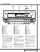
Front Panel Controls 36 ˘ 35 ˆ ¸ ¯˜ AVR 500 Volume Speaker Multi Room Dig. Select Delay COAX DIGITAL TAPE CD DVD VID 1 VID 2 VID 3 6 CH AM/FM TUNING Set PRESET SCAN PRESET TUN MODE PRO LOGIC DIGITAL 3-STEREO VMAx LOGIC 7 C/M THEATER SURR.
Front Panel Controls 8 Video 3 Inputs: These audio/video inputs may be used for temporary connection of video games, camcorders, digital still cameras or portable audio products. To select a source connected to these jacks, press the Vid 3 Input Selector @. 9 Tape Selector: Press this button to select the device connected to the Tape In jacks f as the listening source. ) CD: Press this button to select the device connected to the CD Input jacks ¶ as the listening source.
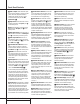
Front Panel Information Display X W MUTE A B C D V SLEEP U T S R Q P TUNED MEMORY PRESET STEREO MONO AUTO COAX 1 2 OPT ANALOG NIGHT DIGITAL 3-STEREO PRO LOGIC VMAx PCM E F LOGIC 7 C LOGIC 7 M THEATER G H IJ K MULTI SURR.
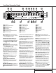
Rear Panel Connections agf e d L R c b a¡™∞ · DIGITAL INPUT IN VIDEO OPTICAL 2 TAPE ¢ ∞ OPTICAL 1 VIDEO 2 ANTENNA COAXIAL 2 GND FM (75Ω) VIDEO 1 DIGITAL OUTPUT OUT SL FL ML (120V.60Hz) TOTAL 150W or 1.5A MAX UNSWITCHED TOTAL 100W or 1A MAX. DVD CENTER FRONT COAXIAL 1 CD AC OUTLETS DIGITAL INPUT OPTICAL 1 DVD CENTER NORTHRIDGE CALIFORNIA, USA VIDEO 2 COAXIAL 1 IN IN VIDEO 1 OUT AM MODEL NO.
Rear Panel Connections ¡ Video 1 Inputs: Connect these jacks to the audio and video PLAY/OUT jacks of a VCR. ™ Video 1 Outputs: Connect these jacks to the audio and video RECORD/IN jacks of a VCR. £ AM Antenna: Connect the AM loop antenna supplied with the receiver to these terminals. If an external AM antenna is used, make connections to the AM and GND terminals in accordance with the instructions supplied with the antenna.
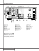
Remote Control Functions a AVR Selector b CD/Tape/DVD Input Selectors c Video Remote Selectors d Power Off Button e Test Tone f Mute g ⁄ / ¤ Buttons h Channel-Select Button i Set Button j ‹ Button k Digital Select l 6-Ch.
Remote Control Functions IMPORTANT NOTE: The AVR 500’s remote may be programmed to control up to eight devices, including the AVR 500. Before using the remote, it is important to remember to press the Device Control Selector button a b c that corresponds to the unit you wish to operate. In addition, the AVR 500’s remote is shipped from the factory to operate the AVR 500 and most Harman Kardon CD or DVD players and cassette decks.
Remote Control Functions v Clear/Macro 4 Button: This button may be used to store and recall a macro; it may also be programmed for use with other devices. (See page 28 for nore information on macros.) w Preset Up/Down: When the tuner is in use, these buttons scroll through the stations that have been programmed into the AVR 500’s memory.
Installation and Connections System Installation After unpacking the unit, and placing it on a solid surface capable of supporting its weight, you will need to make the connections to your audio and video equipment. Audio Equipment Connections We recommend that you use high-quality interconnect cables when making connections to source equipment and recorders to preserve the integrity of the signals.
Installation and Connections NOTE: The AVR 500 will accept both standard (composite) or S-Video signals. However, it will not convert signals from one video format type to the other. AVR 500 and the remote IR link will provide that function. At the AVR 500, plug the audio interconnect cables into the Multi Out jacks • on the AVR 500’s rear panel.
System Configuration Speaker Selection and Placement The placement of speakers in a multichannel home-theater system can have a noticeable impact on the quality of sound reproduced. No matter which type or brand of speakers is used, the same model or brand of speaker should be used for the front-left, center and front-right speakers.
System Configuration System Setup Once the speakers have been placed in the room and connected, the remaining steps in the setup process are to program the AVR 500’s bass management system for the type of speakers used in your system, calibrate the output levels, and set the delay times used by the surround sound processor. You are now ready to power up the AVR 500 to begin these final adjustments. 1. Plug the Power Cable ° into an unswitched AC outlet. 2.
System Configuration 4. Press the ⁄ / ¤ buttons g on the remote or the Selector buttons 34 on the front panel until either LARGE or SMALL appears, matching the type of speakers you have at the left-front and right-front positions, as described by the definitions shown on preceding page. When SMALL is selected, low-frequency sounds will be sent to the subwoofer output only.
System Configuration buttons g until PRO LOGIC appears in the Main Information Display V and the PRO LOGIC indicator G lights up. 2. Press the Test button e on the remote. The words T-T FL 0dB will appear in the Main Information Display V, and the letters FL will flash once each second. NOTE: To use the on-screen display while making output level adjustments, press the OSD button s.
System Configuration To set the delay times, follow these steps: 1. Put the AVR 500 in the Dolby Pro Logic mode by pressing the Dolby Pro Logic Selector Ó on the front panel or by pressing the Surround Mode Selector 31 on the remote, followed by the ⁄ / ¤ ● buttons g until PRO LOGIC appears in the Main Information Display V and the PRO LOGIC indicator G lights up. 2. Press the Delay button i ˜ on the remote or front panel.
Operation Basic Operation Once you have completed the setup and configuration of the AVR 500, it is simple to operate and enjoy. The following instructions should be followed for you to maximize your enjoyment of your new receiver: • When using the AVR 500 for the first time, you must press the Main Power Switch 1 on the front panel to turn the unit on. This places the unit in a Standby mode, as indicated by the amber color of the Power Indicator 3 .
Operation Main Information Display V will now read VFD FULL. the Mute button f ı again to return to normal operation. • Within five seconds, press either of the Selector Buttons 34 to choose either half brightness, as indicated by the display VFD HALF, or completely off with the display blank. You may cycle through all of the options by continually pressing the Selector Buttons 34..
Operation Surround Mode Chart MODE FEATURES DELAY TIME RANGE DOLBY DIGITAL Available only with digital input sources encoded with Dolby Digital data. It provides up to five separate main audio channels and a special dedicated Low-Frequency Effects channel. Center: 0 ms – 5 ms Surround: 0 ms – 15 ms DTS Available only with digital input sources encoded with DTS data.
Operation (continued from page 21) desired mode ( Ó Ô Ò Ú. To select a surround mode using the remote, press the Surround Mode Selector 31 , and then press the ⁄ / ¤ buttons g to change the mode. As you press the buttons, the Surround mode name will appear in the Main Information Display V, and an individual mode indicator will also light up F G H I J K. Note that the Dolby Digital or DTS modes may only be selected when a digital input is in use.
Operation played back with full digital intelligibilty while reducing the minimum peak level by 1/4 to 1/3. This prevents abruptly loud transitions from disturbing others without reducing the impact of the digital source. The Night mode is available only when Dolby Digital signals with special data are being played. discs. The digital circuits in the AVR 500 are capable of high-quality digital-to-analog decoding, and they may be connected directly to the digital audio output of your CD or LD player.
Operation The tuner will run through the list of preset stations, stopping for five seconds at each one. Press the button again to stop the scan at your desired station. • Please make certain that you are aware of any copyright restrictions on any material you copy. Unauthorized duplication of copyrighted materials is prohibited by Federal law.
Multiroom Operation The AVR500 is fully equipped to operate as the control center for a sophisticated multiroom operation with optional remote external InfraRed (IR) sensors, speakers and power amplifiers. Although some multi- room installations will require the services of a specially trained installer, it is possible for the average do-it-yourself hobbyist to install a simple remote room system.
Programming the Remote The AVR 500 is equipped with a powerful remote control that will control not only the receiver’s functions, but also most CD players and cassette decks manufactured by Harman Kardon. For increased flexibility, the remote also contains the codes for most popular brands of audio and video equipment, including CD players, cassette decks, TV sets, cable boxes, VCRs, satellite receivers and other home-theater equipment.
Programming the Remote Programmed Device Functions Once the AVR 500’s remote has been programmed for the codes of other devices, press the appropriate Input or Remote Selector b c to change the remote from control over the AVR 500 to the additional product. When you press any of the Input or Remote Selectors, it will briefly flash in red to indicate that you have changed the device being controlled.
Programming the Remote 1. Press the Input or Remote Selector bc for the unit you wish to have associated with the volume control and the Mute button f at the same time until the red light illuminates under the Device Selector. 2. Press the Volume Up button 32 . 3. Press either the AVR a or the TV Device Control Selector c, depending on which system’s volume control you wish to have attached for the punch-through mode.
Function List No.
Setup Code Tables: TV Manufacturer/Brand Setup Code Number ADMIRAL AKAI AMPRO ANAM AOC CANDLE CAPEHART CENTRONIC CITIZEN CLASSIC CONCERTO CONTEC CRAIG CROWN CURTIS MATHES DAEWOO DAYTRON DWIN DYNATECH ELECTROHOME EMERSON FISHER FUNAI FUTURETECH GE GOLDSTAR HITACHI INFINITY INKEL JBL 072 001 073 043 001 001 058 043 001 043 004 043 054 143 001 004 004 177 062 024 001 007 028 043 004 004 004 164 129 164 081 167 167 054 004 002 161 055 058 003 056 112 004 080 104 002 003 004 101 143 101 103 143 1
Setup Code Tables: TV (continued) Manufacturer/Brand Setup Code Number JC PENNEY JENSEN JVC KENWOOD KLOSS KTV LUXMAN LXI MAGNAVOX MARANTZ MEMOREX METZ MGA MINERVA MITSUBISHI MTC NAD NEC OPTONICA PANASONIC PHILCO PHILIPS PIONEER PORTLAND PROSCAN PROTON QUASAR RADIO SHACK RCA 004 013 034 001 002 043 004 007 001 001 004 088 001 088 004 001 015 001 019 034 001 001 004 004 144 004 034 004 001 32 SETUP CODES 008 024 030 065 101 143 160 038 070 059 143 070 083 015 003 164 007 052 004 160 059 164
Setup Code Tables: TV (continued) Manufacturer/Brand Setup Code Number REALISTIC RUNCO SAMPO SAMSUNG SANYO SCOTT SEARS SHARP SIGNATURE SONY SOUNDESIGN SUPRE MACY SYLVANIA SYMPHONIC TANDY TATUNG TECHNICS TECHWOOD TENIKA TERA TMK TOSHIBA TOTEVISION UNIVERSAL VIDEO CONCEPTS VIDIKRON VIDTECH WARDS YAMAHA YORK ZENITH 007 072 001 004 007 004 004 004 072 070 003 002 001 052 081 056 034 004 002 172 004 015 143 008 146 174 004 004 004 004 072 019 169 004 101 020 028 007 014 047 058 127 021 043 015 019 133 033
Setup Code Tables: VCR Manufacturer/Brand Setup Code Number AIWA ANAM AUDIO DYNAMICS BROKSONIC CANON CAPEHART CRAIG CURTIS MATHES DAEWOO DAYTRON DBX DYNATECH ELECTROHOME EMERSON 129 FISHER FUNAI GE GO VIDEO GOLDSTAR HARMAN KARDON HITACHI INSTANTREPLAY JC PENNEY JENSEN JVC KENWOOD LLOYD LXI MAGNAVOX MARANTZ MARTA MATSUI MEI MEMOREX MGA MINOLTA MITSUBISHI MTC MULTITECH NEC NORDMENDE 034 031 012 035 028 108 001 031 007 108 012 034 059 006 131 001 034 031 132 004 012 018 031 004 043 012 014 034 001 031 012 1
Setup Code Tables: VCR Manufacturer/Brand Setup Code Number OPTONICA PANASONIC PENTAX PHILCO PHILIPS PILOT PIONEER PORTLAND PULSAR QUARTZ RCA REALISTIC RICO SAMSUNG SANSUI SANYO SCOTT SEARS SHARP SHINTOM SONY SOUNDESIGN SYLVANIA SYMPHONIC TANDY TATUNG TEAC TECHNICS TEKNIKA THOMAS TMK TOSHIBA TOTEVISION UNITECH VECTOR RESEARCH VICTOR VIDEO CONCEPTS VIDEOSONIC WARDS YAMAHA ZENITH 053 070 004 031 031 101 004 108 072 014 004 001 058 017 043 001 017 001 031 024 001 034 031 034 010 043 034 031 031 034 006 004
Setup Code Tables: CD Manufacturer/Brand Setup Code Number ADCOM AIWA AKAI CARVER DENON HARMAN KARDON JVC KENWOOD MARANTZ MONDIAL NAD NAKAMICHI ONKYO OPTIMUS PANASONIC PIONEER REALISTIC RCA SHARP SHERWOOD SONY TEAC TECHNICS YAMAHA 062 187 202 003 205 047 022 007 107 147 215 217 038 049 068 010 181 012 013 166 225 062 068 012 042 170 195 167 226 033 136 055 044 005 218 168 085 020 187 150 051 112 097 131 200 054 041 135 138 208 163 023 001 002 137 072 219 030 174 102 066 115 126 015 008 024 Se
Setup Code Tables: DVD/LD Manufacturer/Brand Setup Code Number DAEWOO DENON GOLDSTAR KENWOOD MAGNAVOX OPTIMUS PANASONIC PHILIPS PIONEER RCA REALISTIC SAMSUNG SHARP SONY TECHNICS TOSHIBA YAMAHA 024 030 027 025 026 032 021 026 020 031 032 023 025 022 021 025 033 034 029 028 Setup Code Tables: CABLE Manufacturer/Brand Setup Code Number Remote Control Model PIONEER AMERICAST JERROLD JERROLD PIONEER PIONEER SCIENTIFIC-ATLANTIC TOCOM ZENITH ZENITH 001 005 006 007 002 003 004 010 008 009 BR-200 RT-J22 (
Troubleshooting Guide SYMPTOM CAUSE SOLUTION Unit does not function when Power Switch is pushed • No AC Power • Make certain AC power cord is plugged into a live outlet • Check to see if outlet is switch controlled Display lights, but no sound or picture • Intermittent input connections • Mute is on • Volume control is down • Make certain that all input and speaker connections are secure • Press Mute button • Turn up volume control Unit turns on, but Front-Panel Display does not light up • Display
Technical Specifications Audio Section Stereo Mode Continuous Average Power (FTC) 80 Watts per channel, 20Hz–20kHz, @ < 0.07% THD, both channels driven into 8 ohms Five-Channel Surround Modes Power Per Individual Channel Front L&R channels: 70 Watts per channel, @ < 0.07% THD, 20Hz–20kHz into 8 ohms Center channel: 70 Watts, @ < 0.07% THD, 20Hz–20kHz into 8 ohms Surround channels: 70 Watts per channel, @ < 0.