AVR 340 OM 3/22/06 9:09 AM Page 1 ® Power for the Digital Revolution. ® AVR 340 AUDIO/VIDEO RECEIVER OWNER’S MANUAL AVR 340 DIGITAL LOGIC 7 VID 1 DVD VID 2 CD 3 STEREO DSP VID 3 FMAM HEADPHONE 5 7 CH. STEREO VID 4 TAPE PRO LOGIC SURR.
AVR 340 OM 3/22/06 9:09 AM Page 2 AVR 340 AUDIO/VIDEO RECEIVER 3 4 4 5 8 11 15 16 19 19 21 21 22 23 23 26 28 28 30 30 31 34 34 34 34 34 35 36 38 40 41 42 42 42 42 44 46 48 48 48 49 50 50 50 50 51 53 63 63 64 64 65 66 Introduction Important Safety Information Unpacking Front-Panel Controls Rear-Panel Connections Main Remote Control Functions Zone II Remote Control Functions Installation and Connections System Configuration Speaker Selection and Placement System Setup Using the On-Screen Display Input Se
AVR 340 OM 3/22/06 9:09 AM Page 3 INTRODUCTION Thank you for choosing Harman Kardon®! With the purchase of a Harman Kardon AVR 340, you are about to begin many years of listening enjoyment. Designed to provide all the excitement and detail of movie soundtracks and every nuance of musical selections, the AVR 340 accomplishes its mission by harnessing advanced technologies usually found only in higher-priced receivers.
AVR 340 OM 3/22/06 9:09 AM Page 4 SAFETY INFORMATION Important Safety Information Verify Line Voltage Before Use Your AVR 340 has been designed for use with 120-volt AC current. Connection to a line voltage other than that for which it is intended can create a safety and fire hazard and may damage the unit. If you have any questions about the voltage requirements for your specific model, or about the line voltage in your area, contact your selling dealer before plugging the unit into a wall outlet.
AVR 340 OM 3/22/06 9:09 AM Page 5 FRONT-PANEL CONTROLS ˜ ˆ Ù ı Û Ú Ò AVR 340 DIGITAL LOGIC 7 VID 1 DVD VID 2 CD 3 STEREO DSP VID 3 FMAM HEADPHONE 5 7 CH. STEREO VID 4 TAPE 6 8 CH PRO LOGIC SURR. OFF Optical 4 Coaxial 4 Video 4 1 3 2 5 4 7 6 9 8 !# @) $ ) ( & % ^ * Ô Ó NOTE: To make it easier to follow the instructions that refer to this illustration, a larger copy may be downloaded from the Product Support section for this product at www.harmankardon.com.
AVR 340 OM 3/22/06 9:09 AM Page 6 FRONT-PANEL CONTROLS 6 Speaker Selector: Press this button to begin the process of configuring the unit to match the type of speakers used in your listening room. (See pages 28–30 for more information on speaker setup and configuration.) 7 Surround Mode Group Selector: Press this button to select the top-level group of surround modes. Each press of the button will select the current or last used mode in each of the surround mode groups (e.g.
AVR 340 OM 3/22/06 9:09 AM Page 7 FRONT-PANEL CONTROLS (See page 46 for more information on reassigning the surround back speakers for multiroom use.) The letters inside each box display the active input channels. For standard analog sources, only the L and R will light, indicating a stereo input. For a digital source, the indicators will light to display the channels being received at the digital input. When the letters flash, the digital input has been interrupted.
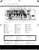
AVR 340 OM 3/22/06 9:09 AM Page 8 REAR-PANEL CONNECTIONS g h f a c e d b U Y W X Z V S O Q T R P M K L N J 0 The Bridge 1 2 3 4 5 6 7 89 A B C D E F G H I NOTE: To make it easier to follow the instructions that refer to this illustration, a larger copy may be downloaded from the Product Support section for this product at www.harmankardon.com.
AVR 340 OM 3/22/06 9:09 AM Page 9 REAR-PANEL CONNECTIONS the remote room. See page 46 for more information on multiroom operation. § Remote IR Carrier Output: The output of this jack is the full signal received at the Remote Sensor Window S, or input through the Remote IR Input ª, including the carrier frequency that is stripped from these signals at the Remote IR Output ‚.
AVR 340 OM 3/22/06 9:09 AM Page 10 REAR-PANEL CONNECTIONS i Video 1 S-Video Input: If the product connected to the Video 1 Audio Inputs a has S-video capability, connect this jack to the PLAY/OUT S-video jack on that unit and then make certain that the S-Video Monitor Output g is connected as described above. j Bridge Digital Media Player (DMP) Connector: With the AVR 340 turned off, connect the optional Harman Kardon Bridge to this connector.
AVR 340 OM 3/22/06 9:09 AM Page 11 MAIN REMOTE CONTROL FUNCTIONS POWER d ON MUTE OFF e f AVR DVD CD VCR CBL/SAT VID2 TV VID3 VID1 g TAPE VID4 h DIM DMP AM/FM 6/8 CH TEST T/V NIGHT M-ROOM 40 i k SLEEP CH. SURR. VOL. 37 M E DE SP K . R CH m 38 NU GU I l 36 n o 41 39 j o SET p q . AY 35 V. CH L DE I n TA L T PR 1 2 3 4 5 6 7 8 TUN-M 9 0 MEM DIRECT CLEAR OSD D.
AVR 340 OM 3/22/06 9:09 AM Page 12 MAIN REMOTE CONTROL FUNCTIONS IMPORTANT NOTE: The AVR 340’s remote may be programmed to control up to eight devices, including the AVR 340. Before using the remote, it is important to remember to press the Input Selector Button e that corresponds to the unit you wish to operate. The AVR 340’s remote is shipped from the factory to operate the AVR 340 and most Harman Kardon CD or DVD players and cassette decks.
AVR 340 OM 3/22/06 9:09 AM Page 13 MAIN REMOTE CONTROL FUNCTIONS u Tuning Up/Down: When the tuner is in use, these buttons will tune up or down through the selected frequency band. If the Tuner Mode Button s& has been pressed so that AUTO appears in the onscreen display and Lower Display Line ı, pressing and holding either of the buttons for three seconds will cause the tuner to seek the next station with acceptable signal strength for quality reception.
AVR 340 OM 3/22/06 9:09 AM Page 14 MAIN REMOTE CONTROL FUNCTIONS compatible VCR, DVD or satellite receiver, pressing this button will switch between the output of the device and the external video input. Consult the owner’s manual for your specific player or receiver for the details of how it implements this function.
AVR 340 OM 3/22/06 9:09 AM Page 15 ZONE II REMOTE CONTROL FUNCTIONS å ∫ POWER A MUTE OFF L AVR VID 1 VID 2 AM/FM VID 3 VID 4 DVD CD TAPE B å Power Off Button: When used in the room where the AVR 340 is located, press this button to place the unit in Standby. When it is used in a remote room with a sensor that is connected to the Multiroom IR Input Jack ∞, this button turns the Multiroom system on and off.
AVR 340 OM 3/22/06 9:09 AM Page 16 INSTALLATION AND CONNECTIONS System Installation After unpacking the unit, locating it in a place with adequate ventilation and placing it on a solid surface capable of supporting its weight, you will need to make the connections to your audio and video equipment.
AVR 340 OM 3/22/06 9:09 AM Page 17 INSTALLATION AND CONNECTIONS remote control is preprogrammed with video recorder product codes for the Video 1 device. 2. Connect the analog audio and video outputs of a satellite receiver, cable TV converter, television set or any other video source to the Video 2 Audio/Video and S-Video Input Jacks Uc.
AVR 340 OM 3/22/06 9:09 AM Page 18 INSTALLATION AND CONNECTIONS System and Power Connections The AVR 340 is designed for flexible use with multiroom system and external control components. Remote Infrared (IR) Control of the AVR or Source Devices If the receiver is placed behind a solid or smoked glass cabinet door, the obstruction may prevent the remote sensor from receiving commands. In this event, an optional remote sensor may be used.
AVR 340 OM 3/22/06 9:09 AM Page 19 SYSTEM CONFIGURATION When all audio, video and system connections have been made, the final steps before listening to your new AVR are to make the configuration adjustments that tailor the unit to the other components in your system as well as to accommodate your personal listening preferences. A few minutes spent to correctly calibrate and configure your system will greatly add to your listening pleasure.
AVR 340 OM 3/22/06 9:09 AM Page 20 SYSTEM CONFIGURATION Video Screen Center Speaker 6.1-Channel System We recommend that you consider adding a second surround back speaker as soon as possible. Front Right Speaker Front Left Speaker 30° 30° 110° Side Surround Left Speaker Surround Speakers for 7.1 Systems For the ultimate home theater experience, a 7.1 surround system uses both traditional surround left/right channels and a surround back left/right speaker pair. In a 7.
AVR 340 OM 3/22/06 9:09 AM Page 21 SYSTEM CONFIGURATION placement should be based on room size and shape and the type of subwoofer used. One method of finding the optimal location for a subwoofer is to begin by placing it in the front of the room, about six inches from a wall, or near the front corner of the room. Another method is to temporarily place the subwoofer at your normal listening position, and then walk around the room until you find a spot where the subwoofer sounds best.
AVR 340 OM 3/22/06 9:09 AM Page 22 SYSTEM CONFIGURATION time-out may be increased to as much as 50 seconds by going to the ADVANCED SELECT menu, and changing the item titled FULL OSD TIME OUT (see page 44). When the full-OSD menu system is used, OSD ON will appear in the Upper Display Line P to remind you that a video display must be used. When the semi-OSD system is used in conjunction with the discrete configuration buttons, the on-screen display will show the current menu selection.
AVR 340 OM 3/22/06 9:09 AM Page 23 SYSTEM CONFIGURATION to change these defaults, press the ¤ Button n to go to the next setting. To change the Component Video assignment, first make certain that the cursor is pointing to the COMPONENT IN line on the menu screen; then press the ‹/› Buttons o until you see the desired input. When the desired component video input has been selected, press the ¤ Button n to go to the next setting.
AVR 340 OM 3/22/06 9:09 AM Page 24 SYSTEM CONFIGURATION * D D L D V S SURROUND O T O S M T L S G P A E BY SELECT * SURROUND IC 7 (SURR) x REO BACK TO MASTER MENU Figure 4 Each of the option lines on this menu (Figure 4) selects the surround mode category, and within each of those categories there will be a choice of the specific mode options. The choice of modes will vary according to the speaker configuration in your system.
AVR 340 OM 3/22/06 9:09 AM Page 25 SYSTEM CONFIGURATION The Night mode may also be adjusted directly any time a compatible Dolby Digital source is playing by pressing the Night Mode Button l. When the button is pressed, D-RANGE OFF will appear in the lower third of the video screen and in the Lower Display Line ı. Press the ⁄¤ Buttons n within 3 seconds to select the desired setting. The last option line in this menu is the setting to turn the unit’s upsampling feature on or off.
AVR 340 OM 3/22/06 9:09 AM Page 26 SYSTEM CONFIGURATION Automated Speaker Setup Using EzSet/EQ The AVR 340 is one of the first receivers in its class to offer automated speaker setup and system calibration.
AVR 340 OM 3/22/06 9:09 AM Page 27 SYSTEM CONFIGURATION by reading the messages that appear in the second line of the menu listing.
AVR 340 OM 3/22/06 9:09 AM Page 28 SYSTEM CONFIGURATION Manual Setup Harman Kardon recommends that you use the EzSet/EQ procedure described on pages 25–27 to configure your receiver for operation. However, you may manually configure your AVR, if you have run EzSet/EQ but wish to make adjustments, if your EzSet/EQ microphone is not available, or if you simply prefer to make your adjustments manually.
AVR 340 OM 3/22/06 9:09 AM Page 29 SYSTEM CONFIGURATION only. If you choose this option and there is no subwoofer connected, you will not hear any low-frequency sounds from the surround channel. When LARGE is selected, a full-range output will be sent to the surround channel outputs, and NO surround channel signals will be sent to the subwoofer output. When NONE is selected, surround sound information will be split between the front left and front right outputs.
AVR 340 OM 3/22/06 9:09 AM Page 30 SYSTEM CONFIGURATION If you wish to customize the speaker settings for each input, make certain that the › cursor is on the BASS MGR line, and press the ‹ / › Buttons o so that INDEPENDENT appears. When this setting is entered by exiting the menu, you may need to go back to the INPUT menu to select another input, and then return to this menu page again to change the settings for that input.
AVR 340 OM 3/22/06 9:09 AM Page 31 SYSTEM CONFIGURATION not be accurate to the inch, as the system is designed to accommodate typical listening rather than a specific “sweet spot” position. Due to the differences in the way each surround mode operates, the delay settings must be established individually for each surround mode.
AVR 340 OM 3/22/06 9:09 AM Page 32 SYSTEM CONFIGURATION Remember that the test tone will circulate to all seven channels; you simply won’t hear any sound when it reaches the right surround back channel. Harman Kardon strongly recommends that you upgrade your speaker system to a 7.1-channel package as soon as you can to achieve the best possible reproduction of all surround programs.
AVR 340 OM 3/22/06 9:09 AM Page 33 SYSTEM CONFIGURATION NOTE: The subwoofer level is not adjustable when the normal test tone is in use. The subwoofer output level may be adjusted when the channel levels are being trimmed to an external program source rather than the test tone, as shown on page 42. Using the Semi-OSD System The output levels may also be adjusted at any time using the remote control and semi-OSD system. To adjust the output levels in this fashion, press the Test Button i.
AVR 340 OM 3/22/06 9:09 AM Page 34 OPERATION Basic Operation Once you have completed the initial setup and configuration of the AVR 340, it is simple to operate and enjoy. The following instructions will help you maximize the enjoyment of your new receiver: Turning the AVR 340 On or Off • When using the AVR 340 for the first time, you must first press the Main Power Switch 1 on the front panel to turn the unit on.
AVR 340 OM 3/22/06 9:09 AM Page 35 OPERATION • To temporarily silence all speaker outputs, press the Mute Button f¬. This will interrupt the output to all speakers and the headphone jack, but it will not affect any recording or dubbing that may be in progress. When the system is muted, the word MUTE will flash in the Upper Display Line P. Press the Mute Button f¬ again to return to normal operation.
AVR 340 OM 3/22/06 9:09 AM Page 36 OPERATION Surround Mode Chart MODE FEATURES Dolby Digital Available only with digital input sources encoded with Dolby Digital data. It provides up to five separate main audio channels and a special dedicated Low-Frequency Effects channel. Dolby Digital EX Available when the receiver is configured for 6.1/7.1-channel operation, Dolby Digital EX is the latest version of Dolby Digital.
AVR 340 OM 3/22/06 9:09 AM Page 37 OPERATION Surround Mode Chart MODE FEATURES Dolby Virtual Speaker Reference Wide Dolby Virtual Speaker uses advanced technology to simulate the sonic signature of a speaker location even when there is no speaker physically present in that location. The Reference (“REF”) mode activates any missing speakers to simulate a 5.1 presentation with accurate localization.
AVR 340 OM 3/22/06 9:09 AM Page 38 OPERATION speakers are capable of reproducing low frequencies, and when you wish to hear the analog source material in its pure form. Digital Audio Playback Digital audio is a major advancement over older analog surround processing systems. It delivers five, six or seven discrete channels: left front, center, right front, left surround, right surround and optionally one or two surround back channels.
AVR 340 OM 3/22/06 9:09 AM Page 39 OPERATION • A “0” indicates that there is no LFE channel information available. However, even when there is no dedicated LFE channel, low-frequency sound will be present at the subwoofer output when the speaker configuration is set to show the presence of a subwoofer. The information in the right side of the display will tell you if the digital audio data contains a special flag signal that will automatically activate the appropriate 6.1 or 7.1 mode.
AVR 340 OM 3/22/06 9:09 AM Page 40 OPERATION Surround Mode Availability for Incoming Bitstreams and Audio Signals For incoming Dolby Digital signals, the following modes are available: Incoming Bitstream Available Surround Modes Dolby Digital 1/0/.0 or 1/0/.1 Dolby Digital, Dolby Digital Stereo, Dolby Virtual Speaker Reference (2 Speaker), Dolby Virtual Speaker Wide (2 Speaker), VMAx (N or F) Dolby Digital 2/0/.0 or 2/0/.
AVR 340 OM 3/22/06 9:09 AM Page 41 OPERATION The boxes around the channel indication letters are used to show which speakers are configured in your system. A small box around the letter indicates that a “Small” speaker has been assigned to that position, while a larger, double box indicates a “Large” speaker assignment. • Some television system broadcasters are not capable of transmitting a 5.1 digital signal.
AVR 340 OM 3/22/06 9:09 AM Page 42 OPERATION Recording In normal operation, the audio or video source selected for listening through the AVR 340 is sent to the record outputs. This means that any program you are watching or listening to may be recorded simply by placing machines connected to the Tape Outputs g or Video 1 or 2 Audio/Video and S-Video Outputs TVbd in the Record mode.
AVR 340 OM 3/22/06 9:09 AM Page 43 OPERATION Simply press the Dim Button h once to dim the front panel to half the normal brightness level; press it again to turn the displays off. Note that when the displays are dimmed or turned off, the blue Power Indicator 2 will remain lit as a reminder that the AVR is still turned on. The accent lighting for the Volume Control Ò will dim when the panel displays are at half brightness.
AVR 340 OM 3/22/06 9:09 AM Page 44 ADVANCED FEATURES The AVR 340 is equipped with a number of advanced features that add extra flexibility to the unit’s operation. While it is not necessary to use these features to operate the unit, they do provide additional options.
AVR 340 OM 3/22/06 9:09 AM Page 45 ADVANCED FEATURES and the Time-Out entry will remain in effect until it is changed, even if the unit is turned off. If you wish to make other adjustments, press the ⁄/¤ Buttons n until the on-screen › cursor is next to the desired setting or the RETURN TO MASTER MENU line and press the Set Button p. If you have no other adjustments to make, press the OSD Button v to exit the menu system.
AVR 340 OM 3/22/06 9:09 AM Page 46 MULTIROOM OPERATION The AVR 340 is fully equipped to operate as the control center for a complete multiroom system that is capable of sending one source to a second zone in the house while a separate source is listened to in the main room. In addition to providing for control over the selection of the remote source and its volume, the AVR 340 offers a comprehensive range of options for powering the speakers in the second zone.
AVR 340 OM 3/22/06 9:09 AM Page 47 MULTIROOM OPERATION If the Remote IR Output Jack ‚ on the AVR 340 is connected to an IR Input jack on compatible Harman Kardon audio components such as CD, DVD or cassette players, the transport functions of those machines may also be controlled using the Transport Controls z`∂é˙î∆˚ on either remote control. To turn the system off from the remote room, press the Power Off Button aå.
AVR 340 OM 3/22/06 9:09 AM Page 48 PROGRAMMING THE MAIN REMOTE The AVR 340 is equipped with a powerful system remote control that will control not only the receiver’s functions, but also most popular brands of audio and video equipment, including CD players, cassette decks, TV sets, cable boxes, VCRs, satellite receivers and other home theater equipment.
AVR 340 OM 3/22/06 9:09 AM Page 49 PROGRAMMING THE MAIN REMOTE 2. Enter the steps for the macro sequence by pressing the button for the actual command step. Although the macro may contain up to 19 steps, each button press, including those used to change devices, counts as a step. The Program Indicator c will flash green to confirm each button press as you enter commands.
AVR 340 OM 3/22/06 9:09 AM Page 50 PROGRAMMING THE MAIN REMOTE • When a button is pressed on the AVR 340 remote, the red light under the Input Selector ef for the product being operated should flash briefly. If the Device Control Selector flashes for some but not all buttons for a particular product, it indicates that no function is programmed for the button being pushed.
AVR 340 OM 3/22/06 9:09 AM Page 51 FUNCTION LIST Name AVR Function DVD CD/CD-R 1 Power On Power On Power On Power On 2 Power Off Power Off Power Off Power Off Power Off TV Power Power Off Power Off Power Off Power Off 3 Mute Mute Mute Mute Mute Mute Mute Mute Mute Mute Mute 4 AVR AVR Select AVR Select AVR Select AVR Select AVR Select AVR Select AVR Select AVR Select AVR Select AVR Select 5 DVD DVD Input Select DVD Select DVD Select DVD Select DVD Select
AVR 340 OM 3/22/06 9:09 AM Page 52 FUNCTION LIST No. Name AVR Function DVD CD/CD-R 45 Tuning Up Tuning Up Next Chapter Track Direct 46 Direct Direct Tuner Entry Angle 47 Clear Clear 48 Preset Up Preset Tune Up Slow Forward +10 49 Tuning Down Tuning Down 50 OSD OSD Program 51 D.
AVR 340 OM 3/22/06 9:09 AM Page 53 SETUP CODE TABLE: TV Manufacturer/Brand Setup Code Number AIWA A MARK ADMIRAL AKAI AMPRO ANAM AOC BLAUPUNKT BROKSONIC CANDLE CAPEHART CENTURION CENTRONIC CITIZEN CLASSIC CONCERTO CONTEC CORANDO CORONADO CRAIG CROWN CURTIS MATHES CXC DAEWOO DAYTRON DIGI LINK DYNASTY DYNATECH ELECTROHOME EMERSON FUNAI FUTURETECH GE GOLDSTAR/LG GRUNDIG HALL MARK HARMAN KARDON HITACHI INFINITY INKEL JBL JC PENNEY JENSEN JVC KAWASHO KEC KENWOOD KMC KTV LLOYTRON LODGENET 027 122 192 123 1
AVR 340 OM 3/22/06 9:09 AM Page 54 SETUP CODE TABLE: TV Manufacturer/Brand Setup Code Number LOGIK LUXMAN LXI MAGNAVOX MARANTZ MATSUI MEMOREX METZ MGA MINERVA MITSUBISHI MTC NATIONAL NEC NIKEI ONKING ONWA OPTONICA ORION PANASONIC PHILCO PHILIPS PIONEER PORTLAND PROSCAN PROTON QUASAR RADIO SHACK RCA REALISTIC RUNCO SAA SAMPO SAMSUNG SANYO SCOTT SEARS SHARP SIEMENS SIGNATURE SONY SOUNDESIGN SPECTRICON SSS SYLVANIA SYMPHONIC TANDY TATUNG TECHNICS TECHWOOD 069 128 077 030 115 148 069 084 115 084 077 175
AVR 340 OM 3/22/06 9:09 AM Page 55 SETUP CODE TABLE: TV Manufacturer/Brand Setup Code Number TEKNIKA TELERENT TERA THOMSON TMK TOSHIBA TOTEVISION VIDEO CONCEPTS VIDTECH WARDS YAMAHA YORK YUPITERU ZENITH ZONDA 045 069 156 190 128 063 132 160 128 069 123 128 045 069 122 069 115 123 128 132 191 129 202 128 128 132 148 090 SETUP CODES 55
AVR 340 OM 3/22/06 9:09 AM Page 56 SETUP CODE TABLE: VCR Manufacturer/Brand Setup Code Number AIWA AKAI AMPRO ASA AUDIO DYNAMICS BROKSONIC CANDLE CANON CAPEHART CITIZEN COMCAST CRAIG DAEWOO DAYTRON DBX DYNATECH EMERSON FISHER FUNAI GE GO VIDEO GOLDSTAR/LG HARMAN KARDON HITACHI JC PENNEY JENSEN JVC KENWOOD LLOYD LXI MAGIN MAGNAVOX MARANTZ MEMOREX MGA MITSUBISHI MULTITECH NAD NATIONAL NEC NORDMENDE OPTIMUS ORION PANASONIC PHILCO PHILIPS PORTLAND PULSAR QUASAR RADIO SHACK RCA 040 048 076 134 018 110 134
AVR 340 OM 3/22/06 9:09 AM Page 57 SETUP CODE TABLE: VCR Manufacturer/Brand Setup Code Number REALISTIC SAMSUNG SANSUI SANYO SCOTT SEARS SHARP SONY SOUNDESIGN SYLVANIA SYMPHONIC TANDY TASHICO TATUNG TEAC TEKNIKA THOMAS TiVo TMK TOSHIBA TOTEVISION UNITECH VECTOR RESEARCH VIDEO CONCEPTS VIDEOSONIC WARDS YAMAHA ZENITH 017 045 048 017 110 017 129 080 040 040 040 017 134 048 040 040 040 002 013 112 045 045 018 018 045 040 018 040 020 040 045 159 SALORA 051 095 105 109 116 147 020 112 020 156 129 020 04
AVR 340 OM 3/22/06 9:09 AM Page 58 SETUP CODE TABLE: CD Manufacturer/Brand ADCOM AIWA AKAI AUDIO TECHNICA AUDIOACCESS AUDIOFILE BSR CALIFORNIA AUDIO CAPETRONIC CARRERA CARVER CASIO CLARINETTE DENON EMERSON FISHER FRABA FUNAI GE GENEXXA GOLDSTAR/LG HAITAI HARMAN KARDON HITACHI INKEL JC PENNEY JENSEN JVC KENWOOD LOTTE LUXMAN LXI MAGNAVOX MARANTZ MCINTOSH MCS MITSUMI MODULAIRE NAD NAKAMICHI NEC NIKKO ONKYO OPTIMUS PANASONIC PHILIPS PIONEER PROTON QUASAR RADIO SHACK RCA 58 Setup Code Number 063 069 072 11
AVR 340 OM 3/22/06 9:09 AM Page 59 SETUP CODE TABLE: CD Manufacturer/Brand RCX REALISTIC SANSUI SANYO SCOTT SHARP SHERWOOD SONY SOUNDSTREAM SYMPHONIC TAEKWANG TEAC THETA DIGITAL TOSHIBA VECTOR RESEARCH VICTOR WARDS YAMAHA YORK Setup Code Number 169 058 093 095 104 047 081 134 157 033 082 095 108 058 105 114 151 003 041 058 105 103 115 116 118 124 059 110 177 011 058 085 086 039 013 074 097 151 087 120 130 095 019 031 053 061 166 105 172 108 164 166 159 133 132 167 180 181 139 163 205 206 2
AVR 340 OM 3/22/06 9:09 AM Page 60 SETUP CODE TABLE: SAT Manufacturer/Brand Setup Code Number ALPHASTAR ALPHASTAR DBS ALPHASTAR DSR BIRDVIEW CHANNEL MASTER CHAPARRAL CITOH DRAKE DX ANTENNA ECHOSTAR ELECTRO HOME FUJITSU GENERAL INSTRUMENT HITACHI DBS HOUSTON TRACKER HUGHES JANIEL JERROLD KATHREIN LEGEND MACOM MAGNAVOX MEMOREX NEXTWAVE NORSAT OPTIMUS PACE DSS PANASONIC PANASONIC DBS PANSAT PERSONAL CABLE PHILIPS PICO PRESIDENT PRIMESTAR RCA RCA DSS REALISTIC SAMSUNG SATELLITE SERVICE CO SCIENTIFIC ATLAN
AVR 340 OM 3/22/06 9:09 AM Page 61 SETUP CODE TABLE: TAPE Manufacturer/Brand HARMAN KARDON Setup Code Number 001 SETUP CODE TABLE: CBL Manufacturer/Brand Setup Code Number ABC ALLEGRO AMERICAST ARCHER BELCOR CABLE STAR CITIZEN COLOUR VOICE DIGI EAGLE EASTERN ELECTRICORD EMERSON FOCUS G.I.
AVR 340 OM 3/22/06 9:09 AM Page 62 SETUP CODE TABLE: CBL Manufacturer/Brand Setup Code Number REMBRANT SAMSUNG SCIENTIFIC ATLANTA SEAM SIGNATURE SPRUCER STARCOM STARGATE TANDY TELECAPATION TEXSCAN TFC TIMELESS TOCOM UNITED CABLE UNIVERSAL VIDEOWAY VIEWSTAR ZENITH ZENTEK 032 003 183 121 001 053 002 120 024 028 036 122 123 170 011 033 124 019 065 116 62 SETUP CODES 072 186 203 221 222 188 081 177 189 011 163 205 034 039 042 113 211 025 086 089 190 125 211 219
AVR 340 OM 3/22/06 9:09 AM Page 63 TROUBLESHOOTING GUIDE SYMPTOM CAUSE SOLUTION Unit does not function when Main Power Switch is pushed • No AC Power • Make certain AC power cord is plugged into a live outlet • Check to see whether outlet is switch-controlled Display lights, but no sound or picture • Intermittent input connections • Make certain that all input and speaker connections are secure • Press Mute Button f¬ • Turn up volume control • Mute is on • Volume control is down No sound from a
AVR 340 OM 3/22/06 9:09 AM Page 64 AVR 340 TECHNICAL SPECIFICATIONS Audio Section Stereo Mode Continuous Average Power (FTC) 70 Watts per channel, 20Hz–20kHz, @ <0.07% THD, both channels driven into 8 ohms Seven-Channel Surround Modes Power per Individual Channel Front L&R channels: 55 Watts per channel @ <0.07% THD, 20Hz–20kHz into 8 ohms Center channel: 55 Watts @ <0.07% THD, 20Hz–20kHz into 8 ohms Surround (L & R Side, L & R Back) channels: 55 Watts per channel @ <0.
AVR 340 OM 3/22/06 9:09 AM Page 65 INDEX 5-Channel Stereo 37, 40 6-Channel/8-Channel Direct Input 11, 14, 34, 35 7-Channel Stereo 23, 37, 40 A-BUS 3, 8, 15, 18, 46, 47 AC Power Connections 4, 8, 9, 16, 18, 21, 34, 63, 64 Advanced Features 46–47 Advanced Select Menu 46 Analog Bypass 25, 35, 37 Antenna Terminals 4, 8, 10, 16, 63 Audio Equipment Connections 16 Audio Setup Menu 23 Auto Mode Tuning 6, 12, 41 Auto Polling 23, 38 Auto Search Method 48 A/V Sync Delay 3, 13, 27, 30, 31 Cable Television 4, 10, 11
AVR 340 OM 3/22/06 9:09 AM Page 66 APPENDIX – SETTINGS WORKSHEET Table 1: Input Settings FEATURE Input Title Component Video Input DVD VIDEO 1 Component Component Video 1 (Y/N) Video2 (Y/N) VIDEO 2 VIDEO 3 Component Video 2 (Y/N) Component Video 2 (Y/N) The Bridge DMP CD TM –––––––––– TAPE TUNER 6/8 CH.
AVR 340 OM 3/22/06 9:09 AM Page 67
AVR 340 OM 3/22/06 9:09 AM Page 68 250 Crossways Park Drive, Woodbury, New York 11797 www.harmankardon.com © 2006 Harman International Industries, Incorporated. All rights reserved. Part No.