® ® Power for the Digital Revolution.
AVR 325 AUDIO/VIDEO RECEIVER 3 4 4 5 7 8 11 14 15 18 18 18 19 20 21 23 24 24 25 26 26 26 26 26 26 27 28 30 31 31 32 32 32 32 32 33 34 34 34 36 36 36 36 36 36 37 38 38 38 39 39 39 40 42 54 54 55 Introduction Important Safety Information Unpacking Front-Panel Controls Front-Panel Information Display Rear-Panel Connections Main Remote Control Functions Zone II Remote Control Functions Installation and Connections System Configuration Speaker Placement System Setup Input Setup Surround Setup Speaker Setup Dela
INTRODUCTION Thank you for choosing Harman Kardon®! With the purchase of a Harman Kardon® AVR 325 you are about to begin many years of listening enjoyment. Designed to provide all the excitement and detail of movie soundtracks and every nuance of musical selections, the AVR 325 is truly a multichannel receiver for the new millennium. The AVR 325 has been engineered so that it is easy to take advantage of all the power of its digital technology.
SAFETY INFORMATION Important Safety Information Verify Line Voltage Before Use Your AVR 325 has been designed for use with 120-volt AC current. Connection to a line voltage other than that for which it is intended can create a safety and fire hazard and may damage the unit. If you have any questions about the voltage requirements for your specific model, or about the line voltage in your area, contact your selling dealer before plugging the unit into a wall outlet.
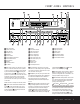
FRONT-PANEL CONTROLS ˘ ˜ ı ¯ ˆ 25 Ò Ú 26 AVR 325 LOGIC 7 VMAx ready 3 1 2 5 4 9 7 6 8 ) @ & % !# $ ^ Ô ( * Ó 1 Main Power Switch 2 System Power Control 3 Power Indicator 4 Headphone Jack 5 Tone Mode 6 Speaker Selector 7 Surround Mode Group Selector 8 Surround Mode Selector 9 Tuning Selector ) ‹ Button ! Tuner Band Selector @ Set Button # › Button $ Preset Station Selector % Input Source Selector ^ Tuner Mode Selector & Optical 3 Digital Input * Coaxial 3 Digital Input ( Video 4
FRONT-PANEL CONTROLS press this button to select Dolby modes, and then press the Surround Mode Selector 8 to choose from the various mode options. 8 Surround Mode Selector: Press this button to select from among the available surround mode options for the major mode group selected. The specific modes will vary based on the number of speakers available, the major mode group and whether the input source is digital or analog.
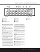
FRONT-PANEL INFORMATION DISPLAY L K A J I H G B C A Upper Display Line B Lower Display Line C OSD Indicator D Multiroom Indicator E Speaker/Channel Input Indicators F PRESET Indicator G MEMORY Indicator H STEREO Indicator I TUNED Indicator J AUTO Indicator A Upper Display Line: Depending on the unit’s status, a variety of messages will appear here. In normal operation, the current audio and video input source information will appear on this line. tion on speaker setup.
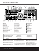
REAR-PANEL CONNECTIONS 41 39 42 40 37 35 33 36 34 32 38 31 k d h f j i e g · b c a fi ‡ ° fl › AVR 325 ¡ ™ £ ¢ ∞ § ¡ AM Antenna ™ FM Antenna £ Preamp Outputs ¢ Subwoofer Output ∞ A-BUS Connector § Surround Speaker Outputs ¶ Front Speaker Outputs • Fan Vents ª Center Speaker Outputs ‚ Surround Back/Multiroom Speaker Outputs ⁄ Switched AC Accessory Outlet ¤ Unswitched AC Accessory Outlet ‹ AC Power Cord Jack › Video Monitor Outputs NOTE: To assist in making the correct connections fo
REAR-PANEL CONNECTIONS positive, or “+,” terminal that should be connected to the red (+) terminal on the Surround Left speaker with older color-coding, while the gray terminal should be connected to the red (+) terminal on the Surround Right speaker with the older color-coding. Connect the black (–) terminal on the AVR to the matching black negative (–) terminals for each surround speaker. (See page 15 for more information on speaker polarity.
REAR-PANEL CONNECTIONS 36 Coaxial Digital Audio Inputs: Connect the coax digital output from a DVD player, HDTV receiver, the S/P-DIF output of a compatible computer sound card playing MP3 files or streams, LD player or CD player to these jacks. The signal may be a Dolby Digital signal, DTS signal or a standard PCM digital source. Do not connect the RF digital output of an LD player to these jacks.
MAIN REMOTE CONTROL FUNCTIONS a Power Off Button b IR Transmitter Window c Program/SPL Indicator d Power On Button e Input Selectors f AVR Selector g AM/FM Tuner Select h 6-Channel/8-Channel Direct Input i Test Button j Sleep Button k Surround Mode Selector l Night Mode m Channel Select Button n ⁄ / ¤ Buttons o ‹ Button p Set Button q Digital Select r Numeric Keys s Tuner Mode t Direct Button u Tuning Up/Down v OSD Button w Dolby Mode Selector x DTS Digital Mode Selector y Logic 7 Mode Select Button z Skip
MAIN REMOTE CONTROL FUNCTIONS IMPORTANT NOTE: The AVR 325’s remote may be programmed to control up to eight devices, including the AVR 325. Before using the remote, it is important to remember to press the Input Selector Button e that corresponds to the unit you wish to operate. In addition, the AVR 325’s remote is shipped from the factory to operate the AVR 325 and most Harman Kardon CD or DVD players and cassette decks.
MAIN REMOTE CONTROL FUNCTIONS v OSD Button: Press this button to activate the On-Screen Display (OSD) system used to set up or adjust the AVR 325’s parameters. w Dolby Mode Selector: This button is used to select from among the available Dolby Surround processing modes. Each press of this button will select one of the Dolby Pro Logic II modes or Dolby 3 Stereo. When a Dolby Digital-encoded source is in use, the Dolby Digital mode may also be selected.
ZONE II REMOTE CONTROL FUNCTIONS POWER A MUTE K OFF AVR VID1 VID2 AM//FM VID3 VID4 DVD CD TAPE DN TUNING UP DN PRESET UP B ∫ AVR Selector: Press this button to turn on the AVR 325. The input in use when the unit was last on will be selected. C D E F G ç AM/FM Tuner Select: Press this button to select the Tuner as the input to the Multiroom system. Press it again to change between the AM and FM bands.
INSTALLATION AND CONNECTIONS System Installation After unpacking the unit, locating it in a place with adequate ventilation and placing it on a solid surface capable of supporting its weight, you will need to make the connections to your audio and video equipment.
INSTALLATION AND CONNECTIONS device should be made to either the Video 2 Audio Inputs 39 or any of the Optical or Coaxial Digital Input Jacks 33 36 . 8. If the component video inputs are used, connect the Component Video Monitor Outputs b to the component video inputs of your TV, projector or display device. 9.
INSTALLATION AND CONNECTIONS The AVR 325 features a removable power cord that allows wires to be run to a complex installation so that the unit itself need not be installed until it is ready for connection. When all connections described above have been made, connect the AC power cord to the AC Power Cord Jack ‹. The AVR 325 draws significantly more current than other household devices, such as computers, that use removable power cords.
SYSTEM CONFIGURATION surround speakers on the sides of the room. Speakers may be placed on a rear wall, behind the listening position. As with the side speakers, rear surrounds should be located so that the bottom of the cabinet is at least two feet higher than the listeners’ ears. The speakers should be no more than six feet behind the rear of the seating area. When all audio, video and system connections have been made, there are a few configuration adjustments that must be made.
SYSTEM CONFIGURATION 4. Install the three supplied AAA batteries in the remote as shown. Be certain to follow the (+) and (–) polarity indicators that are on the top of the battery compartment. MASTER MENU (Figure 1) will appear, and adjustments are made from the individual menus. * I S S D C M A E 5. Turn the AVR 325 on either by pressing the System Power Control 2 on the front panel, or via the remote by pressing the Power On Button d, the AVR Selector f or any of the Input Selectors eg on the remote.
SYSTEM CONFIGURATION When using the full-OSD system to make the setup adjustments, press the OSD Button v once so that the MASTER MENU (Figure 1) appears. The › cursor will be next to the INPUT SETUP line. Press the Set Button p to enter the menu and the INPUT SETUP menu (Figure 2) will appear on the screen.
SYSTEM CONFIGURATION OFF: When OFF is highlighted, the Night mode will not function. MID: When MID is highlighted, a mild compression will be applied. MAX: When MAX is highlighted, a more severe compression algorithm will be applied. We recommend that you select the MID setting as a starting point and change to the MAX setting later, if desired. The Night mode may also be adjusted directly any time a Dolby Digital source is playing by pressing the Night Mode Button l.
SYSTEM CONFIGURATION When SMALL is selected, low-frequency sounds will be sent only to the subwoofer output. If you choose this option and there is no subwoofer connected, you will not hear any low-frequency sounds from the front channels. When LARGE is selected, a full-range output will be sent to the front left and front right outputs. Depending on the choice made in the SUBWOOFER line in this menu, bass information may also be directed to the front left/right speakers, a subwoofer or both.
SYSTEM CONFIGURATION When all initial speaker “size” settings have been made, you now have the option to take advantage of the AVR 325’s Triple Crossover system, which allows individual crossover settings to be made for each speaker grouping. The low-frequency crossover point is set by the design of your speakers.
SYSTEM CONFIGURATION Buttons o 37 so that METER is highlighted. When the change in measurement units is made, press the ⁄/¤ Buttons n to return the › cursor to the CENTER position. ‹/› With the on-screen › cursor pointing to CENTER, press the ‹ / › Buttons o 37 until the distance from the center speaker to the preferred listening position is entered.
SYSTEM CONFIGURATION achieve a desired result. In order to prevent possible damage to your hearing or your equipment, we emphasize that you should avoid setting the master volume above 0dB. NOTE: The subwoofer output is not adjusted when the test tone is in use. To adjust the subwoofer output you must use an external source, following the instructions on page 32.
OPERATION Basic Operation Once you have completed the initial setup and configuration of the AVR 325, it is simple to operate and enjoy. The following instructions will help you maximize the enjoyment of your new receiver: Turning the AVR 325 On or Off • When using the AVR 325 for the first time, you must press the Main Power Switch 1 on the front panel to turn the unit on. This places the unit in a Standby mode, as indicated by the amber color of the Power Indicator 3 .
OPERATION grams bearing the logo of one of the major surroundencoding processes, such as Dolby Surround, DTS Stereo or UltraStereo,® may be played in either the Dolby Digital, Dolby Pro Logic II Cinema, DTS Neo:6 Cinema, or Logic 7 Cinema surround modes depending on the source material. NOTE: Once a program has been encoded with matrix surround information, it retains the surround information as long as the program is broadcast in stereo.
OPERATION Surround Mode Chart MODE FEATURES Dolby Digital Available only with digital input sources encoded with Dolby Digital data. It provides up to five separate main audio channels and a special dedicated Low-Frequency Effects channel. Dolby Digital EX Available when the receiver is configured for 6.1/7.1-channel operation, Dolby Digital EX is the latest version of Dolby Digital.
OPERATION OPTICAL or COAXIAL inputs, as they appear in the Upper Display Line A or on-screen display. When the digital source is playing, the AVR 325 will automatically detect which type of digital data stream is being decoded and display that information in the Upper Display Line A. Digital Bitstream Indicators When a digital source is playing, the AVR 325 senses the type of bitstream data that is present. Using this information, the correct surround mode will automatically be selected.
OPERATION • When a digital source is playing, you may not be able to select some of the analog surround modes such as Dolby Pro Logic II, Dolby 3, Stereo, Hall, Theater or Logic 7. NOTES: • The AVR 325 is only capable of playing signals in the MP3 (MPEG 1/Layer 3) format. It is not compatible with other computer audio codecs. • When a Dolby Digital or DTS source is playing, it is not possible to make an analog recording using the Tape Outputs 35 and Video 1 or Video 2 Audio Outputs 38 41 .
OPERATION Recalling Preset Stations • To manually select a station previously entered in the preset memory, press the Numeric Keys r that correspond to the desired station’s memory location. • To manually tune through the list of stored preset stations one by one, press the Preset Stations Selector Buttons $ 33 © on the front panel or remote. remote to guide you to the correct SPL level. To use the remote for this purpose, press and quickly release the SPL Selector Button 41 to activate the sensor.
ADVANCED FEATURES The AVR 325 is equipped with a number of advanced features that add extra flexibility to the unit’s operation. While it is not necessary to use these features to operate the unit, they provide additional options that you may wish to use. Surround Amplifier Channel Assignment The AVR 325 is equipped with seven full-power amplifier channels to allow for complete 7.1-channel operation without the need for additional external amplifiers.
ADVANCED FEATURES To turn off the semi-OSD system, you’ll need to make an adjustment in the ADVANCED SELECT menu (Figure 10). To start the adjustment, press the OSD Button v to bring the MASTER MENU to the screen. Press the ¤ Button n, until the on-screen › cursor is next to the ADVANCED line. Press the Set Button p to enter the ADVANCED SELECT menu. To change the full-OSD Time-Out, you will need to make an adjustment in the ADVANCED SELECT menu (Figure 10).
MULTIROOM OPERATION The AVR 325 is fully equipped to operate as the control center for a complete multiroom system that is capable of sending one source to a second zone in the house while a separate source is listened to in the main room. In addition to providing for control over the selection of the remote source and its volume, the AVR 325 offers a comprehensive range of options for powering the speakers in the second zone.
MULTIROOM OPERATION When the multiroom system is turned on, the input selected using the multiroom menu will be fed to the Multiroom Audio Outputs j on the rear panel as well as the A-BUS Jack ∞. The volume will be as set in the previous selection, although it may also be adjusted using an optional IR sensor and the Zone II remote in the remote location, or the A-BUS keypad, or on the optional audio power amplifier connected to the Multiroom Audio Outputs j.
PROGRAMMING THE REMOTE The AVR 325 is equipped with a powerful remote control that will control not only the receiver’s functions, but also most popular brands of audio and video equipment, including CD players, cassette decks, TV sets, cable boxes, VCRs, satellite receivers and other home theater equipment.
PROGRAMMING THE REMOTE 4. Press the button on the AVR 325 remote that you wish to program. The Program/SPL Indicator c will stop flashing. 7. When all buttons to be erased have been pressed, press the Learn Button 42 to complete the process. 5. Within five seconds, press and hold the button on the original remote that you wish to “teach” into the AVR 325 remote. When the Program/SPL Indicator c turns green three times, release the button. The Program Indicator will then begin to flash amber again.
PROGRAMMING THE REMOTE Erasing Macro Commands Programmed Device Functions To remove the commands that have been programmed into one of the Macro buttons, follow these steps: Once the AVR 325’s remote has been programmed for the codes of other devices, press the appropriate Input Selector e to change the remote from controlling the AVR 325 to controlling the additional product.
PROGRAMMING THE REMOTE green three times and then go out to confirm the data entry. the device selected by the AVR 325 or the remote. To program the remote for Channel Control PunchThrough, follow these steps: 1. Press the Input Selector Button ef for the device you wish to have the channel control associated with and the Mute Button 43 at the same time until the red light appears under the Input Selector ef and the Program/SPL Indicator c flashes amber. 2. Press the Volume Down Button 40 .
FUNCTION LIST No.
FUNCTION LIST No. Button Name AVR Function DVD CD/CD-R Tape 45 Direct Direct Tuner Entry Angle Random Play 46 Clear Clear Clear Clear 47 Preset Up Preset Tune Up Slow Forward +10 48 Tune Down Tune Down Prev Chapter Track Increment 49 OSD OSD 50 D.
SETUP CODE TABLE: TV Manufacturer/Brand A MARK ADMIRAL AKAI AMPRO AMSTRAD ANAM AOC BLAUPUNKT BROKSONIC CANDLE CAPEHART CENTURION CENTRONIC CITIZEN CLASSIC CONCERTO CONTEC CORANDO CORONADO CRAIG CROWN CURTIS MATHES CXC DAEWOO DAYTRON DIGI LINK DYNASTY DYNATECH ELECTROHOME EMERSON FISHER FUNAI FUTURETECH GE GOLDSTAR GRUNDIG HALL MARK HARMAN KARDON HITACHI INFINITY INKEL JBL JC PENNEY JENSEN JVC KAWASHO KEC KENWOOD KLOSS 42 Setup Code Number 103 132 192 001 160 070 164 053 045 055 057 076 001 011 103 084 205
SETUP CODE TABLE: TV Manufacturer/Brand KMC KTV LLOYTRON LODGENET LOGIK LUXMAN LXI MAGNAVOX MARANTZ MATSUI MEMOREX METZ MGA MIDLAND MINERVA MITSUBISHI MTC NAD NATIONAL NEC NIKEI ONKING ONWA OPTONICA ORION PANASONIC PENNEY PHILCO PHILIPS PIONEER PORTLAND PROSCAN PROTON QUASAR RADIO SHACK RCA REALISTIC RUNCO SAA SAMPO SAMSUNG SANYO SCOTT SEARS SHARP SIEMENS SIGNATURE SONY SOUNDESIGN Setup Code Number 132 001 045 132 162 172 173 069 069 011 013 021 053 077 001 003 011 060 001 074 148 148 013 069 107 084 001 0
SETUP CODE TABLE: TV Manufacturer/Brand SPECTRICON SSS SUPREMACY SYLVANIA SYMPHONIC TANDY TATUNG TECHNICS TECHWOOD TEKNIKA TELEFUNKEN TELERENT TERA THOMSON TMK TOSHIBA TOTEVISION UNIVERSAL VIDEO CONCEPTS VIDTECH WARDS YAMAHA YORK YUPITERU ZENITH ZONDA 44 Setup Code Number 103 011 045 002 001 003 011 060 184 077 057 063 080 011 001 002 003 011 039 047 083 069 156 190 191 011 107 013 021 035 042 132 014 015 160 011 107 011 014 015 025 001 011 107 045 069 070 090 094 103 SETUP CODE TABLES 061 064 065 107 1
SETUP CODE TABLE: VCR Manufacturer/Brand AIWA AKAI AMPRO AMSTRAD ANAM ASA AUDIO DYNAMICS BROKSONIC CANDLE CANON CAPEHART CITIZEN CRAIG CURTIS MATHES DAEWOO DAYTRON DBX DUAL DYNATECH ELECTROHOME EMERSON FERGUSON FINLUX FISHER FUNAI GE GO VIDEO GOLDSTAR GRAETZ HARMAN KARDON HITACHI INSTANT REPLAY ITT JCL JC PENNEY JENSEN JVC KENWOOD LLOYD LXI MAGIN MAGNAVOX MARANTZ MARTA MATSUI MEI MEMOREX MGA MINOLTA Setup Code Number 040 022 048 050 108 076 133 037 039 089 134 018 029 044 048 041 043 110 147 134 135 137 03
SETUP CODE TABLE: VCR Manufacturer/Brand MITSUBISHI MTC MULTITECH NAD NATIONAL NEC NORDMENDE OPTIMUS OPTONICA ORION PANASONIC PENTAX PHILCO PHILIPS PILOT PIONEER PORTLAND PULSAR QUARTZ QUASAR RADIO SHACK RCA REALISTIC RICO RUNCO SABA SAISHO SALORA SAMSUNG SANSUI SANYO SCHAUB LORENZ SCOTT SEARS SHARP SHINTOM SONY SOUNDESIGN STS SYLVANIA SYMPHONIC TANDY TASHICO TATUNG TEAC TECHNICS TEKNIKA TELEFUNKEN THOMAS 46 Setup Code Number 019 026 049 050 133 030 040 139 140 018 029 044 048 048 159 057 058 147 166 070
SETUP CODE TABLE: VCR Manufacturer/Brand THOMSON THORN TMK TOSHIBA TOTEVISION UNITECH VECTOR RESEARCH VICTOR VIDEO CONCEPTS VIDEOSONIC WARDS YAMAHA ZENITH Setup Code Number 136 136 013 015 019 047 051 063 085 098 112 155 045 087 045 018 052 018 040 050 045 003 019 023 030 037 039 040 045 057 058 018 040 044 048 040 052 060 062 076 083 087 112 SETUP CODE TABLES 47
SETUP CODE TABLE: CD Manufacturer/Brand ADC ADCOM AIWA AKAI AUDIO TECHNICA AUDIOACCESS AUDIOFILE BSR CALIFORNIA AUDIO CAPETRONIC CARRERA CARVER CASIO CLARINETTE CROWN CURTIS MATHES DENON EMERSON FISHER FRABA FUNAI GE GENEXXA GOLDSTAR HAITAI HARMAN KARDON HITACHI INKEL JC PENNEY JENSEN JVC KENWOOD KYOCERA LOTTE LUXMAN LXI MAGNAVOX MARANTZ MCINTOSH MCS MEMOREX MGA MISSION MITSUBISHI MITSUMI MODULAIRE NAD NAKAMICHI 48 Setup Code Number 012 049 063 069 072 111 118 156 050 177 184 053 125 211 044 064 015 109 0
SETUP CODE TABLE: CD Manufacturer/Brand NEC NIKKO NSM ONKYO OPTIMUS PANASONIC PHILIPS PIONEER PROTON QUASAR RADIO SHACK RCA RCX REALISTIC ROTEL SAE SAMSUNG SANSUI SANYO SCOTT SEARS SHARP SHERWOOD SIGNATURE SONY SOUNDSTREAM STS SYLVANIA SYMPHONIC TAEKWANG TANDY TEAC TECHWOOD THETA DIGITAL TOSHIBA VECTOR RESEARCH VICTOR WARDS YAMAHA YORK Setup Code Number 021 069 053 055 051 037 038 045 046 020 036 056 057 015 075 109 119 039 051 138 149 017 036 071 094 051 210 015 109 122 126 213 024 049 081 093 169 049 056
SETUP CODE TABLE: TAPE Manufacturer/Brand HARMAN KARDON Setup Code Number 001 SETUP CODE TABLE: AUDIO Manufacturer/Brand HARMAN KARDON Setup Code Number 001 SETUP CODE TABLE: DVD Manufacturer/Brand APEX DIGITAL CALIFORNIA AUDIO DENON GE GOLDSTAR HARMAN KARDON JVC KENWOOD LG LOTTE MAGNAVOX MARANTZ MITSUBISHI NAD ONKYO OPTIMUS PANASONIC PHILIPS PIONEER PROCEED PROSCAN RCA RUNCO SAMSUNG SANYO SHARP SONY TECHNICS THOMSON TOSHIBA YAMAHA ZENITH ZENITH DIVX 50 Setup Code Number 061 040 002 019 022 034 003 00
SETUP CODE TABLE: SAT Manufacturer/Brand ALPHASTAR ALPHASTAR DBS ALPHASTAR DSR AMPLICA BIRDVIEW BSR CAPETRONICS CHANNEL MASTER CHAPARRAL CITOH CURTIS MATHES DRAKE DX ANTENNA ECHOSTAR ELECTRO HOME EUROPLUS FUJITSU GENERAL INSTRUMENT HITACHI DBS HOUSTON TRACKER HUGHES HYTEK JANIEL JERROLD KATHREIN LEGEND LUXOR MACOM MAGNAVOX MEMOREX NEXTWAVE NORSAT OPTIMUS PANASONIC PANASONIC DBS PANSAT PERSONAL CABLE PHILIPS PICO PRESIDENT PRIMESTAR RCA REALISTIC SAMSUNG SATELLITE SERVICE CO SCIENTIFIC ATLANTA SONY STAR CHOI
SETUP CODE TABLE: CBL Manufacturer/Brand ABC ALLEGRO AMERICAST ANTRONIX ARCHER BELCOR CABLE STAR CENTURION CENTURY CITIZEN COLOUR VOICE COMBANO COMTRONICS DIAMOND DIGI EAGLE EASTERN ELECTRICORD EMERSON FOCUS G.I.
SETUP CODE TABLE: CBL Manufacturer/Brand PULSAR RADIO SHACK RCA RECOTON REGAL REGENCY REMBRANT SAMSUNG SCIENTIFIC ATLANTA SEAM SHERITECH SIGNAL SIGNATURE SL MARX SPRUCER STARCOM STARGATE SYLVANIA TADIRAN TANDY TELECAPATION TEXSCAN TFC TIMELESS TOCOM TOSHIBA UNIKA UNITED CABLE UNIVERSAL VIDEOWAY VIEWSTAR ZENITH ZENTEK Setup Code Number 058 111 112 213 053 214 116 055 056 061 099 063 115 032 037 072 186 003 018 047 048 121 029 037 001 188 037 053 081 177 189 002 011 015 016 015 037 120 071 037 024 028 036 07
TROUBLESHOOTING GUIDE SYMPTOM CAUSE SOLUTION Unit does not function when Main Power Switch is pushed • No AC Power • Make certain AC power cord is plugged into a live outlet • Check to see whether outlet is switch-controlled Display lights, but no sound or picture • Intermittent input connections • Make certain that all input and speaker connections are secure • Press Mute Button 43 • Turn up volume control • Mute is on • Volume control is down Unit turns on, but front panel display does not light
AVR 325 TECHNICAL SPECIFICATIONS Audio Section Stereo Mode Continuous Average Power (FTC) 65 Watts per channel, 20Hz–20kHz, @ <0.07% THD, both channels driven into 8 ohms Seven-Channel Surround Modes Power per Individual Channel Front L&R channels: 50 Watts per channel @ <0.07% THD, 20Hz–20kHz into 8 ohms Center channel: 50 Watts @ <0.07% THD, 20Hz–20kHz into 8 ohms Surround (L & R Side, L & R back) channels: 50 Watts per channel @ <0.
® 250 Crossways Park Drive, Woodbury, New York 11797 www.harmankardon.com © 2002 Harman International Industries, Incorporated Part No.