AVR154-OM.
SAFETY INFORMATION Important Safety Instructions 1. 2. 3. 4. 5. 6. Read these instructions. Keep these instructions. Heed all warnings. Follow all instructions. Do not use this apparatus near water. The A/V receiver’s cabinet may be cleaned by gently wiping with a soft cotton or microfiber cloth. Do not use water or any liquid cleaners. 7. Do not block any of the ventilation openings. Install in accordance with the manufacturer’s instructions. 8.
SAFETY INFORMATION Important Safety Information Verify Line Voltage Before Use Your AVR 154 has been designed for use with 120-volt AC current. Connection to a line voltage other than that for which it is intended can create a safety and fire hazard and may damage the unit. If you have any questions about the voltage requirements for your specific model, or about the line voltage in your area, contact your selling dealer before plugging the unit into a wall outlet.
STAPLE INVOICE HERE 4
TABLE OF CONTENTS 2 6 8 10 12 15 16 16 16 16 17 17 17 17 17 18 18 19 20 20 20 20 20 25 25 25 26 27 28 28 28 29 29 29 30 31 31 33 34 34 34 34 34 34 35 35 35 35 36 36 37 37 38 39 39 39 39 40 40 41 41 44 SAFETY INFORMATION INTRODUCTION FRONT-PANEL CONTROLS REAR-PANEL CONNECTIONS REMOTE CONTROL FUNCTIONS INTRODUCTION TO HOME THEATER CONNECTIONS Speaker Connections Subwoofer Connecting Source Devices to the AVR Audio Connections Digital Audio Analog Audio Video Connections Digital Video Analog Video Antennas SP
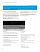
INTRODUCTION Please register your product on our Web site at www.harmankardon.com. Note: You’ll need the product’s serial number. At the same time, you can choose to be notified about our new products and/or special promotions. WWW.HARMANKARDON.
INTRODUCTION Audio Inputs Ease of Use • AM/FM tuner • On-screen display with composite, S-video and component video (480i); choice of blue or black background • CD • Tape • 6-Channel direct • Auxiliary mini-jack Audio/Video Inputs (With S-Video) • Two-line dot-matrix front-panel display • Color-coded connections • Programmable 11-device main remote control • Source input renaming • A/V sync delay up to 100ms • Video 1 • Video 2 Supplied Accessories • DVD The following accessory items are supplied
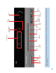
FRONT-PANEL CONTROLS Main Power Switch: This mechanical switch turns the power supply Tuner Band: Press this button to select the tuner as the source, or on or off. It is usually left pressed in (On position), and cannot be turned on using the remote control. to switch between the AM and FM bands. Standby/On Switch: This electrical switch turns the receiver on for playback, or leaves it in Standby mode for quick turn-on using this switch or the remote control.
Main Power Switch Surround Mode Surround Select Tuning Tuner Band Preset Stations Source Select Tuning Mode Headphone Jack Speaker/Channel Input Indicators Digital Audio Inputs (Optical 3 and Coaxial 3) Remote IR Sensor Video 3 Video Inputs Volume Video 3 Analog Audio Inputs NOTE: To make it easier to follow the instructions throughout the manual that refer to this illustration, a copy of this page may be downloaded from the Product Support section at www.harmankardon.com.
REAR-PANEL CONNECTIONS AM and FM Antenna Terminals: Connect the included AM and FM antennas to their respective terminals for radio reception. Front, Center and Surround Speaker Outputs: Use twoconductor speaker wire to connect each set of terminals to the correct speaker. Remember to observe the correct polarity (positive and negative connections). Always connect the positive lead to the colored terminal on the receiver and the red terminal on the speaker.
Subwoofer Output Video Monitor Outputs Front Speaker Outputs HDMI Monitor Output Center Speaker Outputs HDMI Inputs (1, 2 and 3) Coaxial Digital Audio Output Surround 6-Channel Speaker Analog Audio Outputs Inputs DVD A/V Inputs Video 1 A/V Inputs Video 1 A/V Outputs Video 2 A/V Inputs Component Video Inputs (1 and 2) Optical Digital Audio Inputs Coaxial Digital (1 and 2) Audio Inputs (1 and 2) AUX Input Component Video Monitor Outputs AC Power Cord NOTE: To make it easier to follow the ins
REMOTE CONTROL FUNCTIONS The AVR 154 remote is capable of controlling up to 11 devices, including the AVR itself and a device connected to the Auxiliary Input. During the installation process, you may program the codes for each of your source components into the remote. Each time you wish to use the codes for any component, first press the Selector button for that component. This changes the button functions to the appropriate codes.
IR Transmitter Lens Power On Program Indicator AVR Selector Mute Power Off Input Selectors AM/FM Test Tone Sleep 6-Channel Input Selector Volume Controls DSP Surround On-Screen Display Channel Level TV/Video Speaker Setup Navigation Digital Input OK Delay Numeric Keys Tuning Mode Direct Station Entry Tuning Tone Mode Night Mode Track Skip Memory Clear Preset Stations Selectors Disc Skip Macros Surround Mode Selectors Dim Transport Controls NOTE: To make it easier to follow the instructions throu
REMOTE CONTROL FUNCTIONS Tuning Mode: This button toggles between manual (one frequency step at a time) and automatic (seeks frequencies with acceptable signal strength) tuning mode. It also toggles between stereo and mono modes when an FM station is tuned. Memory: After you have tuned a particular radio station, press this button, then the numeric keys, to save that station as a radio preset. Tuning: Press these buttons to tune a radio station.
INTRODUCTION TO HOME THEATER The AVR 154 may be the first multichannel surround sound receiver you have owned. Although it has more connections and features than 2-channel receivers, many of the principles are similar and the new concepts are easy to understand. This introductory section will help you to familiarize yourself with the basic concepts, which will make setup and operation smoother.
CONNECTIONS There are different types of audio and video connections used to connect the receiver to the speakers and video display, and to connect the source devices to the receiver. To make it easier to keep them all straight, the Consumer Electronics Association (CEA) has established a color-coding standard. See Table 1. Bare wire cables are installed as follows (see Figure 2): Table 1 – Connection Color Guide 3. Screw the cap back into place until the wire is held snugly. 1.
CONNECTIONS Audio Connections There are two formats for audio connections: digital and analog. Digital audio signals are required for listening to sources encoded with digital surround modes, such as Dolby Digital and DTS. The AVR 154 uses two types of digital audio connections: coaxial and optical. Either type of digital audio connection may be used for each source device, but never both simultaneously for the same source.
CONNECTIONS The AVR 154 will not convert analog video signals to the HDMI format, and the on-screen displays are not visible when using an HDMI source. Connect the composite or S-video monitor output (or both, depending on which video connections your sources use) to your video display to view the on-screen menus. The physical HDMI connection is simple. The connector is shaped for easy plug-in (see Figure 9).
SPEAKER PLACEMENT Before you begin to connect cables, it is important to place your speakers in their correct locations in the room. The side surround speakers should be placed 110 degrees from the center speaker, that is, slightly behind and angled toward the listener. If this isn’t feasible, place them behind the listener, with each surround speaker facing the opposite-side front speaker. The surround speakers may be placed a little higher than the listener’s ears.
INSTALLATION You are now ready to connect your various components to your receiver. Before beginning, turn off all components, including the AVR 154, and unplug their power cords. Don’t plug any of the power cords back in until you have finished making all of your connections. Step Three – Connect the Antennas Connect the FM and AM antennas to their terminals. See Figure 18. Remember that your receiver generates heat while it is on.
INSTALLATION Video Connections: (choose only one, and make sure that type is available on your TV) • HDMI • Component video • S-video • Composite video NOTES: • Digital audio, HDMI and component video connections are not dedicated to any source input. When any of these physical connections are used, they must be assigned to the desired source input as described in the Initial Setup section. It’s possible for a source input to use none of the connectors named for it; e.g.
INSTALLATION AVR 154 NOTES: • Where a given type of connection is called for, e.g., HDMI, component video or digital audio, you may use any available input of that type. We recommend connections solely because they are assigned by default to certain source inputs. • If you wish to make recordings from a DVD, use the DVD S-video or composite video input, and the DVD Analog Audio inputs in addition to any other connections.
INSTALLATION • Connect the recorder’s optical digital audio output to the Optical 2 Input on the AVR (if available). • Then go to “Composite/S-Video” below to make recordings, as the AVR 154 cannot make recordings from copy-protected component video sources or digital audio (except 2-channel) sources.
INSTALLATION Composite/S-Video: If the best video connection common to both the set-top box and the TV is either S-video or composite video, follow these steps (see Figure 28): To make analog audio recordings, connect the recorder’s left and right analog audio outputs to the Tape Inputs on the AVR, and the recorder’s analog audio inputs to the AVR’s Tape Outputs. • Connect the set-top’s S-video or composite video output (use one connection only) to the corresponding Video 2 Input on the AVR.
INSTALLATION AVR 154 AVR 154 Figure 34 – Component Video Monitor Outputs Figure 32 – Connecting a Device to the Front-Panel Inputs Audio Components: Connect audio-only devices, such as CD players, to either the Coaxial 3 or Optical 3 Digital Audio Inputs, or the Video 3 Analog Audio Inputs (see Figure 32). If you obtain your broadcast programming from the TV, connect its audio outputs to the front-panel inputs and program the AVR remote to operate the TV, as described in Step Eight.
INSTALLATION 3. This step places the remote in program mode. Refer to Figure 37. Press and hold the Input Selector until the LED on the remote starts to flash, then release it. When pressed, the Input Selector will light red briefly, go dark, and then relight when the Program Indicator LED starts to flash. 4. Program the desired device type for any of the three HDMI selectors by pressing the corresponding Input Selector: • Press DVD to operate a DVD player.
INSTALLATION the Remote Control Function List, Table A9 in the Appendix, for each button’s functions with the various product types. You may program Macros, which are preprogrammed code sequences that execute many code commands with a single button press. You may also program “punch-through” codes, which allow the remote to operate the volume, channel or transport controls of another device without having to switch the remote’s device mode.
INITIAL SETUP Before you begin enjoying your new receiver, a few adjustments should be made to configure the AVR 154 to match your actual system. Make sure that you have connected a video display to either the S-video or composite video monitor output on the receiver. When you turn on your display and the AVR, you should see a blue screen. A message may appear briefly at the bottom of the screen. This message is part of the on-screen display system, and is referred to as the “semi-OSD”.
INITIAL SETUP With proper bass management, the AVR 154 divides the source signal at a crossover point. All information above the crossover point is played through the satellite speaker (front left/right, center or surround left/right), and all information below the crossover point is played through the subwoofer. This enables each loudspeaker in your system to perform at its best, delivering an enjoyable sound experience. Find the speaker’s frequency response, which is usually given as a range, e.g.
INITIAL SETUP LEFT/RIGHT: This line tells the AVR 154 the capabilities of your front left and right speakers. Use the ‹ / › Buttons to select either SMALL or LARGE for these speakers. CENTER: Move the cursor to the line for the center speaker, and use the ‹ / › Buttons to select a setting for this speaker.
INITIAL SETUP Setting the Speaker Crossover menu correctly ensures that your speakers sound their best. Although you could skip this step the first time you use the receiver, we recommend that you take the few extra minutes to enter the correct crossover settings. Select from seven possible settings: 40Hz, 60Hz, 80Hz, 100Hz, 120Hz, 150Hz or 200Hz.
INITIAL SETUP sound equally loud at the listening position is a critical step in the setup process. Sit in the listening position, and eliminate external noises for the few minutes needed to calibrate the output levels. You may use a handheld SPL meter (available at most electronics stores) set to the C-Weighting, Slow scale, or you may calibrate the levels by ear. Try to adjust the levels so that all channels sound equally loud.
INITIAL SETUP NOTE: Setting the channel levels while one surround mode is active does not carry over to other modes. After you have set the levels satisfactorily in one mode, note the results and change to other surround modes. For those modes that don’t reflect your level settings, either copy the settings you obtained as a short cut, or re-do the procedure to determine the correct settings for those surround modes. Move the cursor to the TITLE line and press the OK Button. A block cursor will blink.
OPERATION Now that you have installed your system components and completed at least a basic configuration of your receiver, you are ready to begin enjoying your home theater system. Turning On the AVR 154 Gently press the Master Power Switch until the word OFF is no longer visible. The Power Indicator above the two power switches should light up in amber. This indicates that the AVR is in Standby mode and is ready to be turned on.
OPERATION If you wish to return the tone controls to 0, or “flat” response, press the ⁄/¤ Buttons, until the TONE OUT message appears, which preserves any changes you have made to the bass or treble settings for later use. To reactivate your changes, the tone control must again be set to TONE IN. The display will return to normal a few seconds after your last command.
OPERATION The COMPONENT IN line of the Input Setup menu indicates which of the two component video inputs on the AVR 154 is assigned to each source. The default assignments are indicated in Table A2 in the Appendix. As shown, various sources share the component video input assignments, but only one source may be physically connected at a time.
OPERATION 3. Press the Tuner Input Selector (marked AM/FM) on the remote. Press this button again to switch bands. Figure 61 – Storing a Preset Station Figure 58 – Tuner Input Selection Radio stations may be selected in one of four ways (see Figure 59): 1. If you know the frequency number, enter it directly by first pressing the Direct Button on the remote, and then using the Numeric Keys. 2.
OPERATION Selecting a Surround Mode Surround mode selection can be as simple or sophisticated as your individual system and tastes. Feel free to experiment with the many available surround modes on the AVR 154, and you may find a few that become your favorites for certain sources or program types.
ADVANCED FUNCTIONS Much of the AVR 154’s performance is handled automatically, with little intervention required on your part. However, the AVR 154 is a sophisticated component, and is capable of being customized to suit your particular system and your tastes. In this section we describe some of the more advanced adjustments available on the AVR 154. You may save this section for later, when you have become more familiar with your receiver.
ADVANCED FUNCTIONS NOTE: The 6.1-channel signals – Dolby Digital EX and DTS-ES Matrix and Discrete – each include a flag meant to signal the receiver to decode the surround back channel. Since the AVR 154 is only capable of processing and playing 5.1 channels, the indications EX-OFF or ES-OFF, as appropriate, will always appear for 6.1-channel bitstreams. Refer to Table 2 on page 42 for more information on which surround modes are available with different bitstreams.
ADVANCED FUNCTIONS Default Modes During initial use or after a processor reset, the AVR 154 defaults to the Logic 7 Music mode for all analog and PCM audio inputs. Subsequently, when a source input is selected and an analog or PCM signal is received, the AVR will switch to the last surround mode used for that source input/incoming signal combination. Figure 65 – Dolby Surround Menu Screen CENTER WIDTH: This setting affects how vocals sound through the three front speakers.
ADVANCED FUNCTIONS Table 2 – Surround Modes Surround Mode Description Incoming Bitstream or Signal Dolby Digital Provides up to five separate main audio channels and a dedicated low-frequency effects (LFE) channel. May be encoded for Night mode, which allows the user to apply a compression setting that maintains intelligibility of softer passages while reducing the loudness of dynamic passages to avoid disturbing others. • Dolby Digital 1/0/.0 or .1, 2/0/.0 or .1, 3/0/.0 or .1, 2/1/.0 or .1, 2/2/.
ADVANCED FUNCTIONS Table 2 – continued Surround Mode Description Incoming Bitstream or Signal DTS Stereo Delivers a 2-channel downmix of DTS Digital materials, or presents a matrix-encoded surround presentation. • DTS 1/0/.0 or .1, 2/0/.0 or .1, 3/0/.0 or .1, 3/1/.0 or .1, 2/2/.0 or .1, 3/2/.0 or .
ADVANCED FUNCTIONS up only when a button is pressed or a remote command is received, and going dark again 5 seconds after the last command. The VFD FADE TIME OUT feature also causes the display to light up only when a button is pressed or a change in the incoming signal is detected, but the display immediately begins to fade to dark. This setting allows you to program the length of the fade time.
ADVANCED FUNCTIONS For example, if you wish to watch your TV (programmed into the Video 3 Button) while changing channels using your cable box (Video 2), first press and hold the Video 3 Button until the LED flashes. Then press the Volume Down Button, followed by the Video 2 Button. To undo punch-through programming, follow the same steps as above, but press the same Input (or AVR) Selector in Steps 1 and 3.
TROUBLESHOOTING GUIDE SYMPTOM CAUSE SOLUTION Unit does not function when Main Power Switch is pushed • No AC power • Make certain AC power cord is plugged into a live outlet • Check whether outlet is switch-controlled Display lights, but no sound or picture • Intermittent input connections • Make certain that all input and speaker connections are secure • Press Mute Button • Turn up volume control • Turn on source and check its settings • Use Input Setup menu to assign inputs • Mute is on • Volume
APPENDIX Table A1 – Recommended Source Component Connections Device Type AVR 154 Source Input Audio Connections Video Connections VCR, DVR, PVR, TiVo or other audio/video recorder Video 1 • Video 1 Analog (inputs and outputs) and • Any one available coaxial or optical digital audio input with corresponding coax digital output • One of Component Video 2, Video 1 S-Video or Video 1 Composite Video Input • For recording, use Video 1 S-Video or Composite Video Output, and do not use component video conn
APPENDIX Appendix – Default settings, worksheets, remote product codes Table A2 – Source Input Setting Defaults Source DVD HDMI 1 HDMI 2 HDMI 3 Video 1 Video 2 Video 3 AUX CD Tape Title Tuner 6-Channel INT.
APPENDIX Table A5 – Source Input Settings Source DVD HDMI 1 HDMI 2 HDMI 3 Video 1 Video 2 Video 3 AUX CD Tape Title Tuner 6-Channel INT.
APPENDIX Table A7 – Remote Control Codes Source Input Product Type (circle one) Video 1 VCR, PVR, DMC Video 2 Cable, Satellite Video 3 TV HDMI 1 DVD, VCR/PVR/DMC, Cable/Satellite HDMI 2 DVD, VCR/PVR/DMC, Cable/Satellite HDMI 3 DVD, VCR/PVR/DMC, Cable/Satellite DVD DVD CD CD, CD-R Tape Cassette Remote Control Code 2 1 3 4 5 6 7 8 9 10 11 12 13 14 15 16 17 18 19 20 21 22 23 25 24 26 Table A8 – System Settings 28 27 29 Feature Default Setting Your Setting VFD
APPENDIX Table A9 – Remote Control Function List No.
APPENDIX Table A9 – Remote Control Function List – continued No. Button Name AVR Function DVD CD/CD-R Tape 44 Memory Memory Audio or Playlist Time 45 Tuning Up Tuning Up Next Chapter Track Direct 46 Direct Direct Tuner Entry Angle Random Play 47 Clear Clear Clear Clear 48 Preset Up Preset Tune Up Slow Forward +10 49 Tuning Down Tuning Down Prev Chapter Track Increment 50 Tone Tone mode 51 D.
APPENDIX Refer to Tables A10 through A16 when programming the codes for your components into the remote.
APPENDIX Table A10 – continued Table A11 – continued TV Manufacturer/Brand Setup Code Number VCR Manufacturer/Brand Setup Code Number TECHWOOD TEKNIKA TELERENT TERA THOMSON TMK TOSHIBA TOTEVISION VIDEO CONCEPTS VIDTECH WARDS YAMAHA YORK YUPITERU ZENITH ZONDA 128 045 069 156 190 128 063 132 160 128 069 123 128 045 069 122 MARANTZ MEMOREX MGA MITSUBISHI MULTITECH NAD NATIONAL NEC NORDMENDE OPTIMUS ORION PANASONIC PHILCO PHILIPS PORTLAND PULSAR QUASAR RADIO SHACK RCA REALISTIC SALORA SAMSUNG SANSUI SANY
APPENDIX Table A12 – Remote Control Product Codes – CD 55 CD Manufacturer/Brand Setup Code Number CD Manufacturer/Brand Setup Code Number ADCOM AIWA AKAI AUDIO TECHNICA AUDIOACCESS AUDIOFILE BSR CALIFORNIA AUDIO CAPETRONIC CARRERA CARVER CASIO CLARINETTE DENON EMERSON FISHER FRABA FUNAI GE GENEXXA GOLDSTAR/LG HAITAI HARMAN KARDON HITACHI INKEL JC PENNEY JENSEN JVC KENWOOD LOTTE LUXMAN LXI MAGNAVOX MARANTZ MCINTOSH MCS MITSUMI MODULAIRE NAD NAKAMICHI NEC NIKKO ONKYO OPTIMUS PANASONIC PHILIPS PIONEER PR
APPENDIX Table A14 – Remote Control Product Codes – SAT Table A15 – Remote Control Product Codes – TAPE SAT Manufacturer/Brand Setup Code Number TAPE Manufacturer/Brand Setup Code Number ALPHASTAR ALPHASTAR DBS ALPHASTAR DSR BIRDVIEW CHANNEL MASTER CHAPARRAL CITOH DRAKE DX ANTENNA ECHOSTAR ELECTRO HOME FUJITSU GENERAL INSTRUMENT HITACHI DBS HOUSTON TRACKER HUGHES JANIEL JERROLD KATHREIN LEGEND MACOM MAGNAVOX MEMOREX NEXTWAVE NORSAT OPTIMUS PACE DSS PANASONIC PANASONIC DBS PANSAT PERSONAL CABLE PHILIPS P
APPENDIX Table A16 – continued CBL Manufacturer/Brand Setup Code Number SIGNATURE SPRUCER STARCOM STARGATE TANDY TELECAPATION TEXSCAN TFC TIMELESS TOCOM UNITED CABLE UNIVERSAL VIDEOWAY VIEWSTAR ZENITH ZENTEK 001 053 002 120 024 028 036 122 123 170 011 033 124 019 065 116 188 081 177 189 011 163 205 034 039 042 113 211 025 086 089 190 125 211 219 57
AVR 154 TECHNICAL SPECIFICATIONS Audio Section Stereo Mode Continuous Average Power (FTC) 40 Watts per channel, 20Hz–20kHz, @ <0.07% THD, both channels driven into 8 ohms Five-Channel Surround Modes Power per Individual Channel Front L&R channels: 30 Watts per channel @ <0.07% THD, 20Hz–20kHz into 8 ohms Center channel: 30 Watts @ <0.07% THD, 20Hz–20kHz into 8 ohms Surround (L & R Side) channels: 30 Watts per channel @ <0.
NOTES 59
250 Crossways Park Drive, Woodbury, New York 11797 www.harmankardon.com © 2008 Harman International Industries, Incorporated. All rights reserved. Part No.