AVR 7000 Audio/Video Receiver OWNER’S MANUAL ® Power for the digital revolution.
AVR 7000 Audio/Video Receiver 3 4 4 5 7 9 11 14 15 18 20 20 20 21 22 23 25 25 25 25 26 27 29 29 29 30 31 31 31 31 32 33 34 34 34 34 35 35 36 36 37 37 38 39 46 46 47 Introduction Safety Information Unpacking Front Panel Controls Front Panel Information Display Rear Panel Connections Main Remote Control Functions Zone II Remote Control Functions Installation and Connections System Configuration Input Setup Surround Setup Delay Settings Crossover Frequency Speaker Setup Output Level Adjustment Operation Basic
Introduction Thank you for choosing Harman Kardon! With the purchase of a Harman Kardon AVR 7000 you are about to begin many years of listening enjoyment. The AVR 7000 has been custom designed to provide all the excitement and detail of movie sound tracks and every nuance of musical selections.
Safety Information Important Safety Information Verify Line Voltage Before Use Your AVR 7000 has been designed for use with 120-volt AC current. Connection to a line voltage other than that for which it is intended can create a safety and fire hazard and may damage the unit. If you have any questions about the voltage requirements for your specific model, or about the line voltage in your area, contact your selling dealer before plugging the unit into a wall outlet.
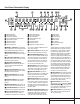
Front Panel Controls ı ˆ Ò ÙÛ Ú Ô Ó ( * & 1 ^ 2 3 4 5 6 7 8 9 ) ! @ #$ % 1 Main Power Switch 2 System Power Control 3 Power Indicator 4 Headphone Jack 5 Selector Buttons 6 Tone Mode 7 Surround Mode Selector 8 Tuning Selector 9 Tuner Band Selector ) Preset Stations Selector ! Input Source Selector @ FM Mode Selector # Bass Control $ Video 4 Input Jacks % Video 4 Status Indicator ^ Treble Control & Balance Control * Volume Control ( Set Button Ó Input Indicators Ô Delay Digital Inpu
Front Panel Controls 7 Surround Mode Selector: Press this button to change the surround mode by scrolling through the list of available modes. Note that depending on the type of input, some modes are not always available. (See page 25 for more information about surround modes.) 8 Tuning Selector: Press the left side of the button to tune lower frequency stations and the right side of the button to tune higher frequency stations.
Front Panel Information Display W X V U T S RQ P A B C D E F G H I J K L M N O A Bitstream Indicators B Dolby Digital Indicator C Coaxial Source Indicators D Analog Dolby Surround Mode Indicators E Optical Source Indicators F Analog Input Indicator G Hall Mode Indicators H VMAx Mode Indicator I Theater Mode Indicator J Logic 7 Mode Indicators K DTS Mode Indicator L Preset Number/Sleep Timer M OSD Indicator N Night Mode Indicator O Multiroom Indicator P Speaker/Channel Input Indicators Q Sl
Front Panel Information Display T Stereo Indicator: This indicator illuminates when an FM station is being tuned in stereo. U Tuned Indicator: This indicator illuminates when a station is being received with sufficient signal strength to provide acceptable listening quality. V Auto Indicator: This indicator illuminates when the tuner’s Auto mode is in use.
Rear Panel Connections j i h g f e d c b a· ° ‡ fl fi › - ¡™ £¢∞§ ¡ AM Antenna ™ FM Antenna £ 6-Channel Direct Inputs ¢ CD Inputs ∞ Component Video Outputs § Video 2 Component Video Inputs ¶ DVD Component Video Inputs • Tape Inputs ª Speaker Outputs ‚ Tape Outputs ¶ • ⁄ Amplifier Inputs ¤ Unswitched AC Accessory Outlet ‹ Switched AC Accessory Outlets › AC Power Cord fi Subwoofer Output fl Preamp Outputs ‡ Digital Audio Outputs ° Coaxial Digital Inputs · Optical Digital Inputs a Remote IR Output
Rear Panel Connections ¡ AM Antenna: Connect the AM loop antenna supplied with the receiver to these terminals. If an external AM antenna is used, make connections to the AM and GND terminals in accordance with the instructions supplied with the antenna. ™ FM Antenna: Connect the supplied indoor or the optional external FM antenna to this terminal. £ 6-Channel Direct Inputs: If an external digital audio decoder is used, connect the outputs of that decoder to these jacks.
Main Remote Control Functions a Program Indicator b AVR Selector c CD/Tape/DVD Input Selectors d Power Off Button e Test Tone f Mute g ⁄ / ¤ Buttons h Channel Select Button i Set Button j ‹ Button k Digital Select l 6-Ch.
Main Remote Control Functions IMPORTANT NOTE: The AVR 7000’s remote may be programmed to control up to eight devices, including the AVR 7000. Before using the remote, it is important to remember to press the Device Control Selector button b c that corresponds to the unit you wish to operate. In addition, the AVR 7000’s remote is shipped from the factory to operate the AVR 7000 and most Harman Kardon CD or DVD players and cassette decks.
Main Remote Control Functions w Preset Up/Down: When the tuner is in use, press these buttons to scroll through the stations programmed into the AVR 7000’s memory. When some source devices, such as CD players, VCRs and cassette decks, are selected using the Device Control Selectors cç, these buttons may function as chapter step or track advance. x Tuning Up/Down: When the tuner is in use, these buttons will tune up or down through the selected frequency band.
Zone II Remote Control Functions å Power Off: When used in the room where the AVR 7000 is located, press this button to place the unit in Standby. When it is used in a remote room with a sensor that is connected to the Multi IR jack b, this button turns the Multi-Room system on and off. ∫ AVR Selector: Press this button to turn on the AVR. The input in use when the unit was last on will be selected.
Installation and Connections System Installation After unpacking the unit, and placing it on a solid surface capable of supporting its weight, you will need to make the connections to your audio and video equipment. Audio Equipment Connections We recommend that you use high-quality interconnect cables when making connections to source equipment and recorders to preserve the integrity of the signals.
Installation and Connections 6. If your DVD player and monitor both have component video connections, connect the component outputs of the DVD player to the DVD Component Video Inputs ¶. Note that even when component video connections are used the audio connections should still be made to either the analog DVD Audio Inputs j or any of the Coaxial or Optical Digital Input jacks °·. 7. If another component video device is available, connect it to the Video 2 Component Video Input jacks §.
Installation and Connections External Audio Power Amplifier Connections If desired, the AVR 7000 may be connected to optional, external audio power amplifiers or used with equalizers or speaker systems that require connection between the preamp and amplifier sections of a receiver. AC Power Connections This unit is equipped with three accessory AC outlets. They may be used to power accessory devices, but they should not be used with highcurrent draw equipment such as power amplifiers.
System Configuration Speaker Selection and Placement The placement of speakers in a multichannel home-theater system can have a noticeable impact on the quality of sound reproduced. No matter which type or brand of speakers is used, the same model or brand of speaker should be used for the front left, center and front right speakers.
System Configuration System Setup Once the speakers have been placed in the room and connected, the remaining steps in the setup process are to program the AVR 7000’s bass management system for the type of speakers used in your system, calibrate the output levels, and set the delay times used by the surround sound processor. You are now ready to power up the AVR 7000 to begin these final adjustments. 1. Plug the Power Cable › into an unswitched AC outlet. 2.
System Configuration the settings for the first input, many settings may be duplicated for the remaining inputs. It is also a good idea to set the configuration data in the order these items are listed in the Main Audio Setup Menu, as some settings require a specific entry in a prior menu item. desired digital input name appears. To return to the ANALOG input, press the buttons until the word analog appears.
System Configuration specific speaker placement and acoustic conditions in your listening room or home theater. The factory setting is appropriate for most rooms, but some installations create an uncommon distance between the front and surround speakers that may cause the arrival of front channel sounds to become disconnected from surround channel sounds. To resynchronize the front and surround channels, follow these steps: 1. Measure the distance from the listening position to the front speakers. 2.
System Configuration only available when specially encoded Dolby Digital signals are played. To adjust the Night mode setting for an input from the menu, make certain that the › cursor is on the Night line of the SURROUND SETUP menu. Next, press ‹/› buttons j 29 to choose between the following settings. OFF: When OFF is in the highlighted video, the Night mode will not function. MID: When MID is in the highlighted video, a mild compression will be applied.
System Configuration Press the ‹/› buttons j 29 on the remote to select the option that best describes your system. Select YES if a subwoofer is connected to your system. Select NO if a subwoofer is NOT connected to your system. Note that when no subwoofer is selected, low frequency sounds below 100Hz will be sent to the front left and front right speakers, provided that the left and right speakers have been set to LARGE. Otherwise, no low frequency sounds will be heard at all.
System Configuration certain that each speaker is connected to the correct output terminal. After checking for speaker placement, let the test noise circulate again, and listen to see which channels sound louder than the others. Using the front left speaker as a reference, press the ‹/› buttons j 29 on the remote to bring all speakers to the same volume level.
Operation Basic Operation Once you have completed the setup and configuration of the AVR 7000, it is simple to operate and enjoy. The following instructions should be followed for you to maximize your enjoyment of your new receiver: • When using the AVR 7000 for the first time, you must press the Main Power Switch 1 on the front panel to turn the unit on. This places the unit in a Standby mode, as indicated by the amber color of the Power Indicator 3 .
Operation Surround Mode Chart MODE FEATURES DELAY TIME RANGE DOLBY DIGITAL Available only with digital input sources encoded with Dolby Digital data. It provides up to five separate main audio channels and a special dedicated Low Frequency Effects channel. Center: 0 ms – 5 ms Initial Setting – 0 ms Surround: 0 ms – 15 ms Initial Setting – 0 ms DTS Available only with digital input sources encoded with DTS data.
Operation programs and standard stereo programs. In all, a total of ten listening modes are available on the AVR 7000. Selection of a surround mode is based on personal taste, as well as the type of program source material being used.
Operation example, DTS bitstreams will cause the unit to switch to DTS decoding, and Dolby Digital bitstreams will enable Dolby Digital decoding. When the unit senses PCM data, as is present from CDs and LDs, the unit will allow the appropriate surround sources to be selected manually. Since the range of available surround modes is dependant on the type of digital data that is present, the AVR 7000 uses a variety of indicators to let you know what type of signal is present.
Operation 5. When a Dolby Digital or DTS source is playing, it is not possible to make an analog recording using the Tape ‚ and VID 1 h record outputs. However, the digital signals will be passed through to the digital audio outputs ‡. PCM Audio Playback PCM (Pulse Code Modulation) is the noncompressed digital audio system used for compact discs and laser discs.
Operation Output Level Trim Adjustment Normal output level adjustment for the AVR 7000 is established using the test tone, as outlined on page 23. In some cases, however, it may be desirable to adjust the output levels using program material such as a test disc, or a selection you are familiar with. Additionally, the output level for the subwoofer can only be adjusted using this procedure.
Advanced Features The AVR 7000 is equipped with a number of advanced features that add extra flexibility to the unit’s operation. While it is not necessary to use these features to operate the unit, they provide additional options that you may wish to use.
Advanced Features the ‹/› buttons j 29 until the desired volume level is shown on the DEFAULT VOL SET line. Note that this setting may not be made with the regular volume controls. NOTE: Since the setting for the turn-on volume cannot be heard while the setting is being made, you may wish to determine the setting before making the adjustment. To do this, listen to any source and adjust the volume to the desired level using the regular volume controls * 32 ˙.
Multiroom Operation The AVR 7000 is fully equipped to operate as the control center for a sophisticated audio/video multiroom system with optional remote external Infrared (IR) sensors, speakers and power amplifiers. Although some multiroom installations will require the services of a specially trained installer, it is possible for the average do-it-yourself hobbyist to install a simple remote room system.
Programming the Remote The AVR 7000 is equipped with a powerful remote control that will control not only the receiver’s functions, but also most popular brands of audio and video equipment, including CD players, cassette decks, TV sets, cable boxes, VCRs, satellite receivers and other home-theater equipment.
Programming the Remote Learning Codes In addition to using codes from the remote’s internal code library, the AVR 7000’s remote is able to “learn” codes from remotes that may not be in the code library. In addition, you may use this function to “learn over” the codes from a preprogrammed device to add functions not included in the preprogrammed codes. To learn or transfer codes from an IR remote to the AVR 7000’s remote, follow these steps: 1.
Programming the Remote Programmed Device Functions Once the AVR 7000’s remote has been programmed for the codes of other devices, press the appropriate Input or Video Selector c 34 to change the remote from controlling the AVR 7000 to controlling the additional product. When you press any one of the selectors, it will briefly flash in red to indicate that you have changed the device being controlled.
Programming the Remote 3. Press either the AVR b or the TV Device Control Selector 34 , depending on which system’s volume control you wish to have attached for the punch-through mode. Note that the red light under the AVR button or Device Control Selector will blink twice and then go out to confirm the data entry. Example: To have the AVR’s volume control activated even though the remote is set to control the TV, first press the TV Device Control Selector bc and the Mute button f at the same time.
Function List No.
Setup Code Tables: TV Manufacturer/Brand Setup Code Number ADMIRAL AKAI AMPRO ANAM AOC CANDLE CAPEHART CENTRONIC CITIZEN CLASSIC CONCERTO CONTEC CRAIG CROWN CURTIS MATHES DAEWOO DAYTRON DWIN DYNATECH ELECTROHOME EMERSON 072 001 073 043 001 001 058 043 001 043 004 043 054 143 001 004 004 177 062 024 001 155 007 028 043 004 004 004 164 129 164 FISHER FUNAI FUTURETECH GE GOLDSTAR HITACHI INFINITY INKEL JBL 081 146 167 056 004 003 080 112 004 104 108 003 004 101 143 004 076 143 101 103 143 114 1
Setup Code Tables: TV (continued) Manufacturer/Brand Setup Code Number JC PENNEY JENSEN JVC KENWOOD KLOSS KTV LUXMAN LXI MAGNAVOX MARANTZ MEMOREX METZ MGA MINERVA MITSUBISHI MTC NAD NEC OPTONICA PANASONIC PHILCO PHILIPS PIONEER PORTLAND PROSCAN PROTON QUASAR RADIO SHACK RCA 004 013 034 001 059 043 004 007 001 001 004 088 001 088 004 001 015 001 019 034 001 001 004 004 144 004 034 004 001 40 SETUP CODES 008 024 030 065 101 143 160 038 070 070 083 143 154 015 003 164 007 052 004 160 059 16
Setup Code Tables: TV (continued) Manufacturer/Brand Setup Code Number REALISTIC RUNCO SAMPO SAMSUNG SANYO SCOTT SEARS SHARP SIGNATURE SONY SOUNDESIGN SUPRE MACY SYLVANIA SYMPHONIC TANDY TATUNG TECHNICS TECHWOOD TEKNIKA TERA TMK TOSHIBA TOTEVISION UNIVERSAL VIDEO CONCEPTS VIDIKRON VIDTECH WARDS YAMAHA YORK ZENITH 007 072 001 004 007 004 004 004 072 070 003 002 001 052 081 056 034 004 002 172 004 015 143 008 146 174 004 004 001 004 072 019 169 004 101 082 028 007 014 127 133 143 160 043 015 019 048
Setup Code Tables: VCR Manufacturer/Brand Setup Code Number AIWA AKAI ANAM AUDIO DYNAMICS BROKSONIC CANON CAPEHART CRAIG CURTIS MATHES DAEWOO DAYTRON DBX DYNATECH ELECTROHOME EMERSON 034 043 031 012 035 028 108 001 031 010 108 012 034 059 005 101 001 034 031 132 004 012 018 031 004 043 012 014 034 001 031 012 101 027 031 001 045 004 004 034 024 012 043 FISHER FUNAI GE GO VIDEO GOLDSTAR HARMAN KARDON HITACHI INSTANTREPLAY JC PENNEY JENSEN JVC KENWOOD LLOYD LXI MAGNAVOX MARANTZ MARTA MATSUI MEI MEMOREX MG
Setup Code Tables: VCR Manufacturer/Brand Setup Code Number OPTONICA PANASONIC PENTAX PHILCO PHILIPS PILOT PIONEER PORTLAND PULSAR QUARTZ RCA REALISTIC RICO SAMSUNG SANSUI SANYO SCOTT SEARS SHARP SHINTOM SONY SOUNDESIGN SYLVANIA SYMPHONIC TANDY TATUNG TEAC TECHNICS TEKNIKA THOMAS TMK TOSHIBA TOTEVISION UNITECH VECTOR RESEARCH VICTOR VIDEO CONCEPTS VIDEOSONIC WARDS YAMAHA ZENITH 053 070 004 031 031 101 004 108 072 014 004 001 058 017 043 001 017 001 031 024 001 034 031 034 010 043 034 031 031 034 006 004
Setup Code Tables: CD Manufacturer/Brand Setup Code Number ADCOM AIWA AKAI CARVER DENON FISHER HARMAN KARDON JVC KENWOOD MARANTZ MONDIAL NAD NAKAMICHI ONKYO OPTIMUS PANASONIC PIONEER REALISTIC RCA SANSUI SHARP SHERWOOD SONY TEAC TECHNICS YAMAHA 062 089 195 041 205 016 001 004 007 044 147 005 217 030 049 068 010 187 017 171 013 096 097 015 008 012 170 202 050 226 187 135 138 139 002 136 016 107 033 163 023 047 208 055 137 178 218 038 085 172 020 215 219 082 168 169 174 021 031 166 126 062
Setup Code Tables: DVD/LD Manufacturer/Brand Setup Code Number DAEWOO DENON GOLDSTAR KENWOOD MAGNAVOX OPTIMUS PANASONIC PHILIPS PIONEER RCA REALISTIC SAMSUNG SHARP SONY TECHNICS TOSHIBA YAMAHA 024 030 027 025 026 032 021 026 020 031 032 023 025 022 021 025 033 034 029 028 Setup Code Tables: CABLE Manufacturer/Brand Setup Code Number Remote Control Model PIONEER AMERICAST JERROLD JERROLD PHILIPS011 PIONEER PIONEER SCIENTIFIC-ATLANTIC SONY TOCOM ZENITH ZENITH 001 005 006 007 012 002 003 004 013 010
Troubleshooting Guide SYMPTOM CAUSE SOLUTION Unit does not function when Main Power Switch is pushed • No AC Power • Make certain AC power cord is plugged into a live outlet • Check to see if outlet is switch-controlled Display lights, but no sound or picture • Intermittent input connections • Mute is on • Volume control is down • Make certain that all input and speaker connections are secure • Press Mute button • Turn up volume control Unit turns on, but Front-Panel Display does not light up • Di
Technical Specifications Audio Section Stereo Mode Continuous Average Power (FTC) 110 Watts per channel, 20Hz–20kHz, @ < 0.07% THD, both channels driven into 8 ohms Five-Channel Surround Modes Power Per Individual Channel Front L&R channels: 100 Watts per channel, @ < 0.07% THD, 20Hz–20kHz into 8 ohms Center channel: 100 Watts, @ < 0.07% THD, 20Hz–20kHz into 8 ohms Surround channels: 100 Watts per channel, @ < 0.
250 Crossways Park Drive, Woodbury, New York 11797 www.harmankardon.com © 1999 Harman Kardon, Incorporated Part No.