AVR 5000 Audio/Video Receiver OWNER’S MANUAL DTS DOLBY D PCM MP3 MUTE RDS PTY CT RT TA AUTO TUNED ST MEMORY PRESET SLEEP O O L 0 C 0 R O O O OPTICAL 1 2 3 DIGITAL COAXIAL 1 2 3 PRO LOGIC ANALOG VMAx NF 5.
Table of Contents 3 4 5 7 9 11 14 15 19 19 20 20 21 21 22 23 23 23 24 24 25 25 27 27 27 27 28 29 29 31 32 33 33 33 34 36 36 36 37 37 38 39 39 40 40 41 42 42 43 43 43 43 44 46 56 56 57 Introduction Safety Information Front Panel Controls Front Panel Information Display Rear Panel Connections Main Remote Control Functions Zone II Remote Control Functions Installation and Connections System Configuration Speaker Selection and Placement First Turn On and Use of OSD Settings to be Made With Each Input Used Inpu
Introduction Thank you for choosing Harman Kardon! With the purchase of a Harman Kardon AVR5000 you are about to begin many years of listening enjoyment. The AVR5000 has been custom designed to provide all the excitement and detail of movie sound tracks and every nuance of musical selections. With onboard Dolby* Digital and DTS† decoding, the AVR5000 delivers six discrete channels of audio that take advantage of the digital sound tracks from the latest DVD and LD releases and Digital Television broadcasts.
Safety Information Important Safety Information Verify Line Voltage Before Use Your AVR5000 has been designed for use with 220-240-Volt AC current. Connection to a line voltage other than that for which it is intended can create a safety and fire hazard and may damage the unit. If you have any questions about the voltage requirements for your specific model, or about the line voltage in your area, contact your dealer before plugging the unit into a wall outlet.
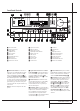
Front Panel Controls ÚÒ Ô Û 29 ˆ ı Ù 30 DTS DOLBY D PCM MP3 MUTE RDS PTY CT RT TA AUTO TUNED ST MEMORY PRESET SLEEP O O L 0 C 0 R O OPTICAL 1 2 3 COAXIAL 1 2 3 DIGITAL PRO LOGIC ANALOG VMAx NF 5.
Front Panel Controls 7 Surround Mode Selector: Press this button to change the surround mode by scrolling through the list of available modes. Note that Dolby Digital and DTS modes can be selected only when a digital input is used (See page 28 for more information about surround modes.) 8 Tuning Selector: Press the left side of the button to tune lower frequency stations and the right side of the button to tune higher frequency stations.
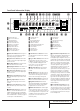
Front Panel Information Display A DTS DOLBY D PCM MP3 Z AE AD YAC AB AA X W V MUTE RDS PTY RT TA AUTO TUNED ST MEMORY PRESET SLEEP Q O O L 0 C 0 R O O O COAXIAL 1 2 3 OPTICAL 1 2 3 B C A B C D E F G H I J K CT U TSR DIGITAL PRO LOGIC D E F Bitstream Indicators Optical Source Indicators DTS Mode Indicator Dolby Digital Indicator Coaxial Source Indicators Dolby Pro Logic Indicator Analog Input Indicator Dolby 3 Stereo Indicator VMAx Mode Indicator 5 Channel Stereo Indicator Logic
Front Panel Information Display S Preset Indicator: This indicator lights when the tuner is in use to show that the Preset Number/Sleep Timer R is showing the station’s preset memory number. (See page 33 for more information on tuner presets.) T Sleep Indicator: This indicator lights when the Sleep function is in use. The numbers in the Preset/Sleep Number Indicators will show the minutes remaining before the AVR5000 goes into the Standby mode. (See page 27 for more information on the Sleep function.
Rear Panel Connections " ! # $ b HDCD®, High Definitioni Compatible Digital and Pacific Microsonics™ are either registered trademarks or trademarks of Pacific Microsonics, Inc. In the United States and/or other countries. HDCD system manufactured under license from Pacific Microsonics, Inc. This product is covered by one or more of the following: in the USA: 5,479,168, 5,638,074, 5,640,161, 5,808,574, 5,838,274, 5,854,600, 5,864,311, 5,872,531, and in Australia: 669114.
Rear Panel Connections Video Monitor Outputs: Connect these jacks to the composite and/or S-Video input of a TV monitor or video projector to view the onscreen menus and the output of any video source selected by the receiver’s video switcher. Remote IR Input: If the AVR5000’s frontpanel IR sensor is blocked due to cabinet doors or other obstructions, an external IR sensor may be used. Connect the output of the sensor to this jack.
Main Remote Control Functions 39 POWER d OFF TM 38 ON e f AVR DVD CD TAPE VCR VID1 TV VID2 CBL/SAT VID3 VID4 LEARN AM/FM 6 CH. SPL g 37 h 36 i 35 j k SLEEP PR SURR. TEST NIGHT VOL. M-ROOM l SP K CH . m 32 31 SET p q 30 AY L DE NO n s RM AL TA L r 1 2 3 4 5 6 7 8 TUN-M 9 0 MEM t 29 28 u v 33 ME N n o 34 R NOTE: The function names shown here are each button’s feature when used with the AVR.
Main Remote Control Functions IMPORTANT NOTE: The AVR5000’s remote may be programmed to control up to seven devices, including the AVR5000. Before using the remote, it is important to remember to press the Input Selector button 4 that corresponds to the unit you wish to operate. In addition, the AVR5000’s remote is shipped from the factory to operate the AVR5000 and most Harman Kardon CD or DVD players and cassette decks.
Main Remote Control Functions J Direct Button: Press this button when the tuner is in use to start the sequence for direct entry of a station’s frequency. After pressing the button simply press the proper Numeric Keys H to select a station (See page 33 for more information on the tuner). Q Preset Up/Down: When the tuner is in use, press these buttons to scroll through the stations programmed into the AVR5000’s memory.
Zone II Remote Control Functions POWER A MUTE OFF K AVR VID1 VID2 AM//FM VID3 VID4 DVD CD TAPE DN TUNING UP DN PRESET UP The Zone II remote may be used in either the same room where the AVR5000 is located, or it may be used in a separate room with an optional infrared sensor that is connected to the AVR5000’s Multi IR input jack %. B C D E F G å Power Off: When used in the room where the AVR5000 is located, press this button to place the unit in Standby.
Installation and Connections After unpacking the unit, and placing it on a solid surface capable of supporting its weight, you will need to make the connections to your audio and video equipment. Audio Equipment Connections We recommend that you use high-quality interconnect cables when making connections to source equipment and recorders to preserve the integrity of the signals.
Installation and Connections 8. If the component video inputs are used, connect the Component Video Output to the component video inputs of your TV, projector or display device. Video Connection Notes: • Y/Pr/Pb Component, S-Video or Composite video signals may only be viewed in their native formats and will not be converted to the other formats. But the OSD can be viewed on the TV screen in any case, with Video or S-Video input selected on the TV.
Installation and Connections Black Black Figure 1: SCART/Cinch-Adapter for playback; signal flow: SCART → Cinch Yellow Yellow Red Red Black Black Red Red Blue 1 Blue Yellow Yellow Figure 2: SCART/Cinch-Adapter for record and playback; signal flow: SCART ↔ Cinch Green 1 Green White White Black Black Figure 3: Cinch/SCART-Adapter for playback; signal flow: Cinch → SCART Yellow Yellow Red Red Rot Red Figure 4: SCART/S-Video Adapter for playback; signal flow: SCART → Cinch Schwarz Black S-Video InIn S
Installation and Connections System and Power Connections The AVR5000 is designed for flexible use with multiroom systems, external control components and power amplifiers. Main Room Remote Control Extension If the receiver is placed behind a solid or smoked glass cabinet door, the obstruction may prevent the remote sensor from receiving commands. In this event, the remote sensor of any Harman Kardon or other compatible device, not covered by the door, or an optional remote sensor may be used.
System Configuration Speaker Selection No matter which type or brand of speakers is used, the same model or brand of speaker should be used for the front-left, center and front-right speakers. This creates a seamless front soundstage and eliminates the possibility of distracting sonic disturbances that occur when a sound moves across mismatched front-channel speakers.
System Configuration First Turn On and Use of the OSD Once the speakers have been placed in the room and connected, the remaining steps are to program the system configuration memories. With the AVR5000 two kind of memories are used, those associated individually with the input selected, e.g. surround modes, and others working independently from any input selected like speaker output levels, crossover frequencies or delay times used by the surround sound processor.
System Configuration Input Setup The first step in configuring the AVR5000 is to select an input. This may be done by pressing the front panel Input Source Selector ! until the desired input’s name appears momentarily in the Main Information Display Y, and the green LED lights next to the input’s name in the front panel Input Indicators . The input may also be selected by pressing the appropriate Input Selector on the remote control 46.
System Configuration Speaker Setup This menu tells the AVR5000 which type of speakers are in use. This is important as it adjusts the settings that determine which speakers receive low frequency (bass) information. For each of these settings use the L A R G E setting if the speakers for a particular position are traditional full-range loudspeakers that are capable of reproducing sounds below 100Hz.
System Configuration At this line you will select the frequency at which bass information is directed to the Subwoofer Output . The choices available will depend on the setting made previously for the front left/right speakers.
System Configuration and the surround speakers are 1 m away, the optimal delay time is figured as (3–1)x3+15=21. Thus, in this example, the Pro Logic delay should be set at twenty milliseconds. NOTE: The DTS, Logic 7, 5CH Stereo, Hall and Theater modes use a fixed, nonadjustable delay time. The Dolby Digital Mode also includes a separate setting for the center channel delay mode, since the discrete nature of these signals makes the location of the center channel speaker more critical.
System Configuration Using EzSet Harman Kardon’s exclusive EzSet remote makes it possible to quickly and accurately set the AVR5000’s output levels without the use of a sound pressure meter, although manual adjustment is also available. However, for the easiest set-up, follow these steps while seated in the listening position that will be used most often: 8.
System Configuration Continue to adjust the individual speakers until they all have the same volume. Note that adjustments should be made with the ‹/› buttons E! on the remote only, NOT the main volume controls. You may also adjust the output levels manually while using the level indication feature of the EzSet remote. To activate the sensor and indicator, simply press and release the SPL Indicator Select button & on the remote while the test tone is circulating.
Operation Basic Operation Once you have completed the setup and configuration of the AVR5000, it is simple to operate and enjoy. The following instructions should be followed for you to maximize your enjoyment of your new receiver: Turning the AVR5000 On or Off • When using the AVR5000 for the first time, you must press the Main Power Switch 1 on the front panel to turn the unit on. This places the unit in a Standby mode, as indicated by the amber color of the Power Indicator 3.
Operation Surround Mode Chart MODE FEATURES DELAY TIME RANGE DOLBY DIGITAL Available only with digital input sources encoded with Dolby Digital data. It provides up to five separate main audio channels and a special dedicated Low Frequency Effects channel. Center: 0 ms – 5 ms Initial Setting – 0 ms Surround: 0 ms – 15 ms Initial Setting – 0 ms DTS Available only with digital input sources encoded with DTS data.
Operation Surround Mode Selection One of the most important features of the AVR5000 is its ability to reproduce a full multichannel surround sound field from digital sources, analog matrix surround encoded programs and standard stereo or even mono programs. In all, a total of thirteen listening modes are available on the AVR5000. Selection of a surround mode is based on personal taste, as well as the type of program source material being used.
Operation Playback from PCM sources may also benefit from the Logic 7. When playing a stereo or surround-encoded PCM source, such as an LD or CD or a PCM audio track from DVD, use the Logic 7 C or Cinema mode. For stereo or surround encoded pure music recordings use the Logic 7 M or Music mode for a wider front sound stage (see Surround Mode Chart page 28).
Operation can be played with all surround modes, also with the most effective Logic 7. ® : When this indicator lights in conjunction with the PCM indicator, the CD that is playing is encoded using the special High Definition Compatible Digital® process. HDCD® discs use 20-bit encoding and other proprietary processing to provide the ultimate in CD listening. Note that HDCD processing is only available in the Stereo or Surround Off mode.
Operation In addition to the rear panel digital outputs, the AVR 5000 offers Harman Kardon’s exclusive configurable front panel output jack feature. For easy connection of portable devices, you may switch the front panel Digital Coax jack % or the Video 4 jack ^ from an input to an output by following these steps: 1. Press the OSD button L to view the MASTER M E N U (Figure 1). 2. Press the Set button F to enter the IN/OUT SETUP menu (Figure 2). 3.
Operation 6-Channel Direct Input Tuner Operation The AVR5000 is equipped for future expansion through the use of optional, external adapters for formats that the AVR5000 may not be capable of processing. When an adapter is connected to the 6-Channel Direct Input , you may select it by pressing the 6-Ch Direct Input Selector '.
Operation RDS Operation The AVR5000 is equipped with RDS (Radio Data System), which brings a wide range of information to FM radio. Now in use in many countries, RDS is a system for transmitting station call signs or network information, a description of station program type, text messages about the station or specifics of a musical selection, and the correct time.
Operation • JAZZ: Jazz Music • COUNTRY: Country Music • NATIONAL: National Music • OLDIES: Oldies Music • FOLK M: Folk Music • DOCUMENT: Documentary Programs • TEST: Emergency Test NOTE: Many stations do not transmit a specific PTY. The display will show NONE, when such a station is selected and PTY is active. NOTE: Some stations transmit constant traffic information. To identify as traffic station, they transmit a specific traffic code constantly, which causes the TA Indicator AA to light in the display.
Advanced Features The AVR5000 is equipped with a number of advanced features that add extra flexibility to the unit’s operation. While it is not necessary to use these features to operate the unit, they provide additional options that you may wish to use. Display Brightness The AVR5000’s front panel Main Information Display Û is set at a default brightness level that is sufficient for viewing in a normally lit room.
Advanced Features Semi-OSD Settings The semi-OSD system places one line messages at the lower third of the video display screen whenever the Volume, Input Source, Surround mode or tuner frequency of any of the configuration settings are changed. The semi-OSD system is helpful in that enables you to have feedback on any control changes or remote commands using the video display when it is difficult to view the front-panel displays.
Multiroom Operation The AVR5000 is fully equipped to operate as the control center for a multiroom system with optional remote external Infrared (IR) sensors, speakers and power amplifiers. Although some multi-room installations will require the services of a specially trained installer, it is possible for the average do-it-yourself hobbyist to install a simple remote room system.
Programming the Remote The AVR5000 is equipped with a powerful remote control that will control not only the receiver’s functions, but also most popular brands of audio and video equipment, including CD players, TV sets, cable boxes, VCRs, satellite receivers and other home-theater equipment. Once the AVR5000’s remote is programmed with the codes for the products you own, it is possible to eliminate most other remotes and replace them with the convenience of a single universal remote control.
Programming the Remote Code Readout Learning Codes from a Remote When the code has been entered using the Auto Search method, it is always a good idea to find out the exact code so that it may be easily reentered if necessary. You may also read the codes to verify which device has been programmed to a specific Control Selector button. In addition to using codes from the remote’s internal code library, the AVR5000’s remote is able to “learn” codes from remotes that may not be in the code library.
Programming the Remote To erase all codes that have been programmed to all devices in the remote, follow these steps: 1. Press any Input Selector 456 and also the Learn button 7. 2. When the red LED under the Input Selector turns red and the Program/SPL Indicator 2 flashes amber, release the buttons. 3. Press and release the same Input Selector 456 again. 4. Press the 9 button H three times. 5.
Programming the Remote Programmed Device Functions Once the AVR5000’s remote has been programmed for the codes of other devices, press the appropriate Input Selector 4 to change the remote from control over the AVR5000 to the additional product. When you press any of these buttons, it will briefly flash in red to indicate that you have changed the device being controlled. When operating a device other than the AVR5000, the controls may not correspond exactly to the function printed on the remote or button.
Programming the Remote Channel Control Punch-Through The AVR 5000’s remote may be programmed to operate so that the channel control function for either the TV, cable or satellite receiver used in your system may be used in conjunction with one of the other devices controlled by the remote. For example, while using and controlling the VCR, you may wish to change channels on a cable box or satellite receiver without having to change the device selected by the AVR 5000 or the remote.
Function List 2 1 3 4 5 6 7 8 9 10 11 12 13 14 15 16 17 18 19 20 21 22 23 26 24 25 27 29 28 31 32 30 33 34 35 36 37 38 39 40 41 42 43 44 45 46 47 48 49 50 51 52 53 54 55 56 57 58 59 60 61 62 63 64 LIGHT 5000 44 FUNCTION LIST No.
Function List No. Button Name Tape VCR (VID 1) TV (VID 2) CBL (VID 3) SAT(VID 3) 1 2 3 4 5 6 7 8 9 10 11 12 13 14 15 16 17 18 19 20 21 22 23 24 25 26 27 28 29 30 31 32 33 34 35 36 37 38 39 40 41 42 43 44 45 46 47 48 49 50 51 52 53 54 55 56 57 58 59 60 61 62 63 64 Power Off Power On Mute AVR DVD CD Tape VID 1 VID 2 VID 3 VID 4 Learn AM/FM 6 Ch.
Setup Code Table: TV Maker (Brand) Name AIWA AKAI ALBA AMSTRAD ARC EN CIEL ARCAM ASTRA ATLANTIC AUDIOSONIC BANG & OLUFSEN BARCO BEKO BLAUPUNKT BRANDT ELECTRONIQUE BRION VEGA BRIONVEGA BRITANNIA BRUNS BSR BUSH BUSH(UK) CGE CLATONIC CONDOR CROWN CTC CLATRONIC DAEWOO DECCA(UK) DUAL DUAL-TEC DUMONT DUMONT-FINLUX DYNATRON ELBE ELTA EMERSON EUROPHON EXPERT FERGUSON FIDELITY(UK) FINLANDIA FINLUX FISHER FUJITSU FUNAI GEC GEC(UK) GOLDSTAR GOODMANS GORENJE GRAETZ GRANADA GRANADA(UK) GRUNDIG 46 SETUP CODES Code Numb
Setup Code Table: TV (continued) Maker (Brand) Name HANSEATIC HIFIVOX HITACHI IMPERIAL INTERVISION INTERFUNK ITT ITT-NOKIA JVC KARCHER KATHREIN KENDO KORTING LOEWE LOEWE OPTA LUXOR MAGNADYNE MARANTZ MARELLI METZ MINERVA MITSUBISHI MULTITECH MURPHY(UK) NAD NATIONAL NEC NECKERMANN NOKIA NORDMENDE OCEANIC OCEANIC(F) OPTONICA ORION OSAKI OTTO VERSAND PANASONIC PATHE' CINEMA PATHE' CINEMA(F) PATHE' MARCONI PHILCO PHILIPS PHOENIX PIONEER PROLINE PROTECH QUELLE RADIOLA RADIOMARELLI RANK Code Number (3digit) List
Setup Code Table: TV (continued) Maker (Brand) Name RBM(UK) REDIFFUSION REDIFFUSION(UK) REDIFUSION REX RFT ROADSTAR ROTEL RTF SABA SALORA SAMPO SAMSUNG SANYO SBR SCHAUB LORENZ SCHNEIDER SCOTT SEG SELECO SHARP SIEMENS SILVER SINGER SONY SOUND WAVE STANDARD STERN TANDBERG TANDY TEC TELEFUNKEN TELETECH TELETON TENSAI THOMSON THORN THORN-FERGUSON TOSHIBA TRISTAR TRIUMPH UHER ULTRAVOX UNIVERSUM VESTEL VOXSON WALTHAM WATSON WATT RADIO WEGA WEGA COLOR WELTBLICK 48 SETUP CODES Code Number (3digit) List 147 059 10
Setup Code Table: TV (continued) Maker (Brand) Name WESTINGHOUSE WESTON YOKO ZANUSSI Code Number (3digit) List 063 094 272 168 050 195 036 040 063 071 079 095 110 138 171 236 260 262 278 293 116 090 121 092 148 103 152 124 133 149 150 155 120 121 136 144 158 129 137 140 147 120 121 136 144 069 144 155 073 090 127 094 148 100 155 104 108 122 130 131 135 138 049 053 054 103 107 143 146 147 148 149 Setup Code Table: VCR Maker (Brand) Name AIWA AKAI AKURA ALBA AMSTR
Setup Code Table: VCR (continued) Maker (Brand) Name FISHER FUJITSU FUNAI GRANADA(UK) GBC(UK) GEC GOLDSTAR GOODMANS GRAETZ GRAETZ(ITT) GRANADA GRANADA(UK) GRUNDIG HANSEATIC HARMAN/KARDON HIFIVOX HITACHI IMPERIAL INTERFUNK INTERVISION ITT ITT/NOKIA ITT-NOKIA JENSEN JVC KARCHER KENDO KENWOOD KOENIG KOERTING KUBA LLOYD LOEWE LOEWE OPTA LUXOR MAGNADYNE MAGNAVOX MARANTZ MEMOREX METZ MINERVA MITSUBISHI MULTITECH NATIONAL NEC NECKERMANN NESCO NOKIA NORDMENDE OCEANIC (ITT) OPTONICA ORION OSAKI OTTO VERSAND PALLADIU
Setup Code Table: VCR (continued) Maker (Brand) Name PANASONIC PATHE' MARCONI PHILIPS PIONEER PROLINE QUELLE RADIOLA RCA REALISTIC REDIFFUSION REX ROADSTAR SABA SALORA SAMSUNG SANSUI SANYO SBR SCHAUB LORENZ SCHNEIDER SEG SELECO SHARP SIEMENS SINGER SONY SUNSTAR SUPERTEC SYLVANIA TANDBERG TEAC TEC TECHNICS TELEFUNKEN TELERENT TENSAI THOMSON THORN THORN-FERGUSON TOSHIBA TRANSONIC UHER ULTRAVOX UNITECH UNIVERSUM W.
Setup Code Table: CD Maker (Brand) Name AIWA AKAI ARCAM AUDIOMECA BSR CALIFORNIA AUDIO CAPETRONIC CROWN DENON FISHER FUNAI GOLDSTAR (LG) GRUNDIG HAITAI HARMAN KARDON HITACHI JVC KENWOOD KYOCERA LINN LUXMAN MAGNAVOX MARANTZ MBL MCINTOSH MERIDIAN MISSION MITSUBISHI MITSUMI NAD NAIM NAKAMICHI NEC ONKYO PANASONIC PHILIPS PIONEER PRIMARE PROTON REALISTIC REVOX ROTEL SAE SAMSUNG SANSUI SANYO SHARP SHERWOOD SIGNATURE SONY T&A TEAC TECHNICS THETA DIGITAL THOMSON 52 SETUP CODES Code Number (3 Digit) List 072 111 1
Setup Code Table: CD (continued) Maker (Brand) Name THORENS TOSHIBA UNIVERSUM (QUELLE) YAMAHA Code Number (3 Digit) List 220 013 074 097 151 155 220 222 223 019 031 053 061 135 173 169 Setup Code Table: CBL Maker (Brand) Name BT CABLE CABLETIME CLYDE CABLE VISION DECSAT CANAL FILMNET FRANCE TELECOM GEC JERROLD MOVIE TIME NSC PHILIPS PIONEER SALORA SAMSUNG SATBOX SCIENTIFIC ATLANTA STS TELESERVICE TUDI UNITED CABLE VISIOPASS WESTMINSTER CABLE ZENITH Code Number (3digit) List 007 008 011 012 016 017 010 0
Setup Code Table: SAT Maker (Brand) Name AIWA AKAI ALBA AMSTRAD ANKARO ASTRA ASTRO BLAUPUNKT BRUNS BUSH BUSH(UK) CAMBRIDGE CAMBRIDGE ARD200 ECHOSTAR ELTASAT FERGUSON FINLUX FTE FUBA G SAT GALAXIS GOLDSTAR GOODMANS GRAETZ GRANADA GRUNDIG HIRSCHMANN HITACHI HUTH IMPERIAL ITT ITT-NOKIA KATHREIN KOSMOS LEMON LENCO LOEWE LORENZEN LUXOR MARANTZ MASPRO METZ MINERVA MITSUBISHI MULTISTAR NEC NOKIA NORSAT OTTO VERSAND PACE PACE MSS SERIES PANASONIC PHILIPS PTT TELECOM QUADRAL QUELLE 54 SETUP CODES Code Number (3dig
Setup Code Table: SAT (continued) Maker (Brand) Name RADIOLA RADIX SAKURA SALORA SAMSUNG SAT SCHAUB LORENZ SCHNEIDER SIEMENS SKY MASTER SKYLAB TANDBERG TANDY TECHNISAT TELECOM TELEFUNKEN THORN-FERGUSON VORTEC WISI ZEHNDER ZENITH Code Number (3digit) List 053 047 054 057 034 068 088 095 099 080 127 132 127 088 099 053 038 090 133 121 008 085 122 005 006 028 047 084 041 083 023 045 048 052 053 082 083 132 142 004 022 026 027 047 080 127 044 120 130 131 102 103 063 064 067 123 127 131 Setup Code T
Troubleshooting Guide SYMPTOM CAUSE SOLUTION Unit does not function when Main Power Switch is pushed • No AC Power • Make certain AC power cord is plugged into a live outlet • Check to see if outlet is switch controlled Display lights, but no sound or picture • Intermittent input connections • Make certain that all input and speaker connections are secure • Press Mute button • Turn up volume control • Mute is on • Volume control is down Sound is heard, but Front-Panel Display does not light • Disp
Technical Specifications Audio Section Stereo Mode Continuous Average Power (FTC) 80 Watts per channel, 20Hz–20kHz, @ < 0.07% THD, both channels driven into 8 ohms Five-Channel Surround Modes Power Per Individual Channel Front L&R channels: 70 Watts per channel, @ < 0.07% THD, 20Hz–20kHz into 8 ohms Center channel: 70 Watts, @ < 0.07% THD, 20Hz–20kHz into 8 ohms Surround channels: 70 Watts per channel, @ < 0.
250 Crossways Park Drive, Woodbury, New York 11797 www.harmankardon.com Harman Consumer International: 2, route de Tours, 72500 Château-du-Loir, France © 2000 Harman Kardon, Incorporated Part No.