® Power for the Digital Revolution.
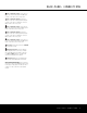
AVR 335 AUDIO/VIDEO RECEIVER 3 4 4 5 7 10 13 14 16 16 16 17 18 20 22 24 25 27 27 27 27 28 28 29 31 32 32 33 33 33 33 33 34 34 35 35 35 35 37 37 37 37 37 37 38 39 39 39 39 40 41 43 53 53 54 55 Introduction Safety Information Unpacking Front-Panel Controls Rear-Panel Connections Main Remote Control Functions Zone II Remote Control Functions Installation and Connections System Configuration Speaker Placement System Setup Input Setup Surround Setup Automated Speaker Setup Using EzSet+ Speaker Setup Delay Setti
INTRODUCTION Thank you for choosing Harman Kardon®! With the purchase of a Harman Kardon AVR 335, you are about to begin many years of listening enjoyment. Designed to provide all the excitement and detail of movie soundtracks and every nuance of musical selections, the AVR 335 harnesses advanced technologies usually found only in higher-priced receivers. The AVR 335 has been engineered so that it is easy to take advantage of all the power of its digital technology.
SAFETY INFORMATION Important Safety Information Verify Line Voltage Before Use Your AVR 335 has been designed for use with 120-volt AC current. Connection to a line voltage other than that for which it is intended can create a safety and fire hazard and may damage the unit. If you have any questions about the voltage requirements for your specific model, or about the line voltage in your area, contact your selling dealer before plugging the unit into a wall outlet.
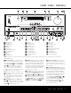
FRONT-PANEL CONTROLS 1 Main Power Switch 2 Power Indicator 3 Standby/On Switch 4 Headphone Jack 5 Tone Mode 6 Speaker Selector 7 Surround Mode Group Selector 8 Surround Mode Selector 9 Tuning Selector ) ‹/› Buttons ! Tuner Band Selector @ Set Button # Digital Input Selector $ Preset Station Selector % Delay Adjust Selector ^ Input Source Selector & Tuner Mode Selector * Optical 4 Digital Input ( Coaxial 4 Digital Input Ó Video 4 Video Input Jacks Ô Video 4 Audio Input Jacks Bass Control Ò Balance Contr
FRONT-PANEL CONTROLS 49 8 Surround Mode Selector: Press this button to select from among the available surround mode options for the mode group selected. The specific modes will vary based on the number of speakers available, the mode group and if the input source is digital or analog. For example, press the Surround Mode Group Selector 7 to select a mode grouping such as Dolby or Logic 7, and then press this button to see the specific mode choices available.
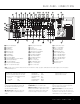
REAR-PANEL CONNECTIONS 40 41 39 37 32 34 36 38 35 33 k i g e c 31 j h f d a b · ° ‡ ¡ ™ £ ¢ ∞ § 49 48 ¶ ª • ¡ Multiroom Audio Outputs ™ CD Audio Inputs £ Tape Outputs ¢ Remote IR Input ∞ Multiroom IR Input § Remote IR Output ¶ Preamp Outputs • Subwoofer Output ª Front Speaker Outputs ‚ Surround Back/Multiroom Speaker Outputs ⁄ Surround Speaker Outputs ¤ Center Speaker Output ‹ Component Video Monitor Outputs › Video 2 Component Video Inputs NOTE: To make it easier to follow the instructions
REAR-PANEL CONNECTIONS ¶ Preamp Outputs: Connect these jacks to an optional, external power amplifier for applications where higher power is desired. • Subwoofer Output: Connect this jack to the linelevel input of a powered subwoofer. If an external subwoofer amplifier is used, connect this jack to the subwoofer amplifier input. ª Front Speaker Outputs: Connect these outputs to the matching + or – terminals on your left and right speakers.
45 44 43 42 39 38 41 40 6 7 8 9 0 1 6 7 8 9 0 1 25 45 24 23 44 22 39 21 38 20 25 24 23 45 22 44 21 39 20 38 37 36 43 35 42 34 41 33 40 32 37 36 35 43 34 42 33 41 32 40 6 7 8 9 0 1 6 25 45 24 44 23 22 39 43 21 38 42 20 25 41 24 40 23 37 22 36 43 21 35 42 20 34 41 33 40 32 43 37 42 36 37 43 36 42 35 34 41 33 40 32 37 7 8 9 0 41 35 34 40 33 37 32 36 35 34 43 33 42 32 41 40 37 36 35 34 33 32 3637 3536 3435 3334 3233 REAR-PANEL CONNECTIONS 37 36 35 34 33 41 47 40 46 39 45 38 44 Video 1 43 51 50 49
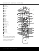
MAIN REMOTE CONTROL FUNCTIONS ON 41 MUTE OFF e f g h AVR DVD CD TAPE VCR VID1 TV VID2 CBL/SAT VID3 VID4 DIM AM/FM 6/8 CH TEST T/V NIGHT M-ROOM 40 i 39 j k SLEEP CH. SURR. VOL. 37 ME N E SP K . R CH m 36 n o 38 U GU ID l o SET p q . L DE .
MAIN REMOTE CONTROL FUNCTIONS IMPORTANT NOTE: The AVR 335’s remote may be programmed to control up to eight devices, including the AVR 335. Before using the remote, it is important to remember to press the Input Selector Button e that corresponds to the unit you wish to operate. In addition, the AVR 335’s remote is shipped from the factory to operate the AVR 335 and most Harman Kardon CD or DVD players and cassette decks.
MAIN REMOTE CONTROL FUNCTIONS been pressed so that AUTO appears in the onscreen menu and Lower Display Line ¯, pressing and holding either of the buttons for 3 seconds will cause the tuner to seek the next station with acceptable signal strength for quality reception. When MANUAL appears in the Lower Display Line ¯, pressing these buttons will tune stations in single-step increments. (See page 31 for more information.
ZONE II REMOTE CONTROL FUNCTIONS POWER A MUTE K OFF AVR VID1 VID2 AM//FM VID3 VID4 DVD CD TAPE DN TUNING UP DN PRESET UP B ∫ AVR Selector: Press this button to turn on the AVR 335. The input in use when the unit was last on will be selected. C D E F G ç AM/FM Tuner Select Button: Press this button to select the Tuner as the input to the Multiroom system. Press it again to change between the AM and FM bands.
INSTALLATION AND CONNECTIONS 300-ohm-to-75-ohm adapter to make the connection. System Installation After unpacking the unit, locating it in a place with adequate ventilation and placing it on a solid surface capable of supporting its weight, you will need to make the connections to your audio and video equipment.
INSTALLATION AND CONNECTIONS 47 45 46 44 37 7 36 6 26 7 27 6 28 29 6 30 7 31 8 43 42 39 41 45 38 43 40 44 37 25 42 39 36 24 41 38 23 40 35 22 37 34 25 21 36 33 24 32 20 35 23 your television so that you may take advantage of the fact that the remote control is preprogrammed with codes for the Video 3 41 47 product 51 37 television If you are only using the teldevice. 46 50 36 40IMPORTANT: evision a display 35 39as 45 49 device (i.e.
SYSTEM CONFIGURATION When all audio, video and system connections have been made, there are a few configuration adjustments that must be made. A few minutes spent to correctly configure and calibrate the unit will greatly add to your listening experience. Speaker Selection and Placement The placement of speakers in a multichannel home theater system can have a noticeable impact on the quality of sound reproduced.
SYSTEM CONFIGURATION 4. Install the three supplied AAA batteries in the remote as shown. Be certain to follow the (+) and (–) polarity indicators that are on the top of the battery compartment. ** I S S D C M E A N U P E H U z D P R E L A L S V MASTER MENU U R A A N T E A P E T S J T O K Y N I T N S UN ER A EL -R + CE ETU D S SE DJU AD OOM ** LECT UP T UST D Figure 1 5.
SYSTEM CONFIGURATION When using the full-OSD system to make the setup adjustments, press the OSD Button v once so that the MASTER MENU (Figure 1) appears. The › cursor will be next to the INPUT SETUP line. Press the Set Button p to enter the menu and the INPUT SETUP menu (Figure 2) will appear on the screen. Press the ‹/› Buttons o until the desired input name appears in the highlighted video, as well as being indicated in the front-panel Input Indicators ı.
SYSTEM CONFIGURATION the surround mode and control over digital upsampling, when available. * DOLBY MODE:DOLBY C D P N U E I A I P N M N G S T E O H A BACK E N R T M SURROUND R WIDTH:SION :AMA ::O PLING :TO * DIGITAL F - F - SURROUND -- of the room, or a deeper presentation that appears to move the center of the sound field toward the back of the room.
SYSTEM CONFIGURATION with two-channel music, surround-encoded programs or standard two-channel programming of any type, respectively. For 6.1/7.1 configurations, the Music and Cinema modes may be selected. The Logic 7 modes are not available when either Dolby Digital or DTS digital soundtracks are in use. See page 29 for a complete explanation of the Logic 7 modes.
SYSTEM CONFIGURATION front right/surround right/surround left) and a subwoofer, press the ‹/› Navigation Buttons o so that 5.1 appears to the right of MEASUREMENT, and then press the Set Button p to start EzSet+. To stop the calibration process at any time, press the ⁄/¤ Navigation Buttons n to move the on-screen cursors to the MEASUREMENT line; press the ‹/› Navigation Buttons o so that STOP appears and press the Set Button p.
SYSTEM CONFIGURATION operate AVR 335. For those situations where you may wish to make a change to the settings entered by EzSet+, follow the instructions on the following pages. Speaker Setup This menu tells the AVR 335 which type of speakers are in use. This is important as it adjusts the settings that decide whether your system will use the “5-channel” or “6-channel/7-channel” modes, as well as determining which speakers receive low-frequency (bass) information.
SYSTEM CONFIGURATION When you have completed your selections for the main surround channels, press the ¤ Button n on the remote to move the cursor to SURR BACK. This line serves two functions in that it not only configures the setting for the surround back channels when they are present; it also tells the AVR 335’s processing system to configure the unit for either 5.1 or 6.1/7.1 operation. When MAIN appears on this line, the system is configured for 7.
SYSTEM CONFIGURATION that is higher in frequency than your subwoofer is capable of reproducing. To prevent unwanted sounds from being sent to subwoofers that cannot handle them and which do not have a built-in low-pass filter, the LFE option line enables you to select a setting for the low-pass filter that is part of the subwoofer feed from the LFE channel. The settings available are the same as those tied to any one of the four available speaker positions on this menu.
SYSTEM CONFIGURATION However, if you have a digital video source or a digital video display that causes lack of lip sync you may use the A/V Sync adjust feature to delay the audio signal as it is sent to all channels (as opposed to the individual settings) so that the picture and sound are brought back together. We recommend that this adjustment be made using the direct access controls on the remote, as shown below.
SYSTEM CONFIGURATION nels sound louder than the others. Using the front left speaker as a reference, press the ‹/› Navigation Button o to bring all speakers to the same volume level. When the ‹/› Navigation Button o is pushed, the test noise circulation will pause on the channel being adjusted to give you time to make the adjustment. When you release the button, the circulation will resume after five seconds. 6.
OPERATION Basic Operation Once you have completed the initial setup and configuration of the AVR 335, it is simple to operate and enjoy. The following instructions will help you maximize the enjoyment of your new receiver: Turning the AVR 335 On or Off • When using the AVR 335 for the first time, you must press the Main Power Switch 1 on the front panel to turn the unit on. This places the unit in a Standby mode, as indicated by the amber color of the Power Indicator 2.
OPERATION to confirm that no processing is being used. When the headphone plug is removed, the audio feed to the speakers will be restored. • When the headphones are in use, you may take advantage of the Dolby Headphone modes to bring added spaciousness to headphone listening. Press the Dolby Mode Select Button w or the Surround Mode Group Selector 7 to cycle through the three Dolby Headphone modes and select the one that you prefer.
OPERATION Surround Mode Chart MODE Dolby Digital Dolby Digital EX DTS 5.1 DTS-ES 6.1 Matrix DTS-ES 6.1 Discrete Dolby Pro Logic II Movie Music Pro Logic Dolby Pro Logic IIx Music Movie Logic 7 Cinema Logic 7 Music Logic 7 Enhance FEATURES Available only with digital input sources encoded with Dolby Digital data. It provides up to five separate main audio channels and a special dedicated low-frequency effects (LFE) channel. Available when the receiver is configured for 6.1/7.
OPERATION IMPORTANT NOTE: Many DVD players have a default setting that does not pass through the DTS data, even though the machine is capable of doing so. If your DVD player has the “DTS Digital Out” logo but does not trigger DTS playback in the AVR 335, change the player’s settings in the “Audio” or “Bitstream” configuration menu so that DTS playback is enabled. The method for doing this will vary with each player. In some cases, the proper menu choice will be “Original,” while in others it will be “DTS.
OPERATION Speaker/Channel Indicators In addition to the bitstream indicators, the AVR 335 features a set of unique channel-input indicators that tell you how many channels of digital information are being received and/or whether the digital signal is interrupted (see Figure 12). Figure 12 These indicators are the L/C/R/LFE/SL/SR/SBL/SBR letters that are inside the center boxes of the Speaker/ Channel Input Indicators ˆ on the front panel.
49 48 47 46 35 4937 34 4836 33 3526 32 3427 31 3328 30 3229 29 3130 28 3031 29 28 OPERATION 49 48 47 45 46 44 43 42 turns off the test tone and allows you to use external source material as the reference. Then, use the ⁄/¤ Buttons n to select the channels to be adjusted. At each channel position, use the ‹ / › Buttons o to change the output level. The goal is to have the output level at each channel equal when heard at the listening position.
ADVANCED FEATURES The AVR 335 is equipped with a number of advanced features that add extra flexibility to the unit’s operation. While it is not necessary to use these features to operate the unit, they provide additional options that you may wish to use. Front-Panel Display Fade In normal operation, the front-panel displays and indicators remain on at full brightness, although you may also dim them or turn them off as shown in the next section.
ADVANCED FEATURES To turn off the semi-OSD system, you’ll need to make an adjustment in the ADVANCED SELECT menu (Figure 13). To start the adjustment, press the OSD Button v to bring the MASTER MENU to the screen. Press the ¤ Button n, until the on-screen › cursor is next to the ADVANCED line. Press the Set Button p to enter the ADVANCED SELECT menu.
MULTIROOM OPERATION The AVR 335 is fully equipped to operate as the control center for a complete multiroom system that is capable of sending one source to a second zone in the house while a separate source is listened to in the main room. In addition to providing for control over the selection of the remote source and its volume, the AVR 335 offers a comprehensive range of options for powering the speakers in the second zone.
MULTIROOM OPERATION To turn the system off from the remote room, press the Power Off Button aå. Remember that the AVR 335 may be turned on or off from the remote room, regardless of the system’s operation or status in the main room. NOTE: When the tuner is selected as the source for the remote zone, any change to the frequency or preset will also change the station being listened to in the main room, if the tuner is in use there.
PROGRAMMING THE REMOTE The AVR 335 is equipped with a powerful remote control that will control not only the receiver’s functions, but also most popular brands of audio and video equipment, including CD players, cassette decks, TV sets, cable boxes, VCRs, satellite receivers and other home theater equipment.
PROGRAMMING THE REMOTE 49 48 35 34 33 32 31 30 29 28 c will flash green to confirm each button press as you enter commands. 47 45 43 NOTE: While entering commands for Power On/Off of 46 any44device 42during a macro sequence, press the Mute 3. Within ten seconds, press the Surround Mode Selector/Channel Down Button k. 37 Button 39 41 . DO NOT press the actual Power button. 37 41 47 51 36 38 40 47 press 45 the43 3. When all the steps have been49 entered, 46 the50commands.
PROGRAMMING THE REMOTE • When a button is pressed on the AVR 335 remote, the red light under the Input Selector ef for the product being operated should flash briefly. If the Device Control Selector flashes for some but not all buttons for a particular product, it does NOT indicate a problem with the remote but rather that no function is programmed for the button being pushed. 49 47 45 43 Volume Punch-Through 48 46 4944 4742 45 43 2. Press the Play Button `.
PROGRAMMING THE REMOTE 49 47 45 43 Example: To use the Video 4 button to operate 46 the44Video424 Input first press a satellite receiver, 48 37 Button 39 41 at the the Mute Selector e and 35 same time until the 34 red light glows 37 41 36 38under 40the Video 4 Button e. Press the VID2/SAT Button e, 36 40 33 26 25 37 followed by the three-digit code for the specific 35 39 32 27 24 36 model you wish to control. Finally, press the 31 28 23 35 34 38 Video 4 Button e again.
FUNCTION LIST No.
FUNCTION LIST No. Button Name AVR Function DVD CD/CD-R Next Chapter Track Direct Tape VCR (VID1) CBL (VID2) SAT (VID2) TV (VID3) Cancel PPV Cancel Sleep FAV FAV Clear Bypass Next Music Alt OSD OSD OSD OSD 44 Tune Up Tune Up 45 Direct Direct Tuner Entry Angle Random Play 46 Clear Clear Clear Clear 47 Preset Up Preset Tune Up Slow Forward +10 48 Tune Down Tune Down Prev Chapter Track Increment 49 OSD OSD 50 D.
SETUP CODE TABLE: TV Manufacturer/Brand Setup Code Number AIWA A MARK ADMIRAL AKAI AMPRO ANAM AOC BLAUPUNKT BROKSONIC CANDLE CAPEHART CENTURION CENTRONIC CITIZEN CLASSIC CONCERTO CONTEC CORANDO CORONADO CRAIG CROWN CURTIS MATHES CXC DAEWOO DAYTRON DIGI LINK DYNASTY DYNATECH ELECTROHOME EMERSON FUNAI FUTURETECH GE GOLD STAR/LG GRUNDIG HALL MARK HARMAN KARDON HITACHI INFINITY INKEL JBL JC PENNEY JENSEN JVC KAWASHO KEC KENWOOD KMC KTV LLOYTRON LODGENET 027 122 192 123 164 045 122 084 205 123 059 123 045 045
SETUP CODE TABLE: TV Manufacturer/Brand Setup Code Number LOGIK LUXMAN LXI MAGNAVOX MARANTZ MATSUI MEMOREX METZ MGA MINERVA MITSUBISHI MTC NATIONAL NEC NIKEI ONKING ONWA OPTONICA ORION PANASONIC PHILCO PHILIPS PIONEER PORTLAND PROSCAN PROTON QUASAR RADIO SHACK RCA REALISTIC RUNCO SAA SAMPO SAMSUNG SANYO SCOTT SEARS SHARP SIEMENS SIGNATURE SONY SOUNDESIGN SPECTRICON SSS SYLVANIA SYMPHONIC TANDY TATUNG TECHNICS TECHWOOD 069 128 077 030 115 148 069 084 115 084 077 175 148 115 045 045 045 077 207 087 045 033
SETUP CODE TABLE: TV Manufacturer/Brand Setup Code Number TEKNIKA TELERENT TERA THOMSON TMK TOSHIBA TOTEVISION VIDEO CONCEPTS VIDTECH WARDS YAMAHA YORK YUPITERU ZENITH ZONDA 045 069 156 190 128 063 132 160 128 069 123 128 045 069 122 069 115 123 128 132 191 129 202 128 128 132 148 090 SETUP CODES 45
SETUP CODE TABLE: VCR Manufacturer/Brand Setup Code Number AIWA AKAI AMPRO ASA AUDIO DYNAMICS BROKSONIC CANDLE CANON CAPEHART CITIZEN CRAIG DAEWOO DAYTRON DBX DYNATECH EMERSON FISHER FUNAI GE GO VIDEO GOLD STAR/LG HARMAN KARDON HITACHI JC PENNEY JENSEN JVC KENWOOD LLOYD LXI MAGIN MAGNAVOX MARANTZ MEMOREX MGA MITSUBISHI MULTITECH NAD NATIONAL NEC NORDMENDE OPTIMUS ORION PANASONIC PHILCO PHILIPS PORTLAND PULSAR QUASAR RADIO SHACK RCA REALISTIC 040 048 076 134 018 110 134 135 094 134 045 017 094 018 040 013
SETUP CODE TABLE: VCR Manufacturer/Brand Setup Code Number SALORA SAMSUNG SANSUI SANYO SCOTT SEARS SHARP SONY SOUNDESIGN SYLVANIA SYMPHONIC TANDY TASHICO TATUNG TEAC TEKNIKA THOMAS TiVo TMK TOSHIBA TOTEVISION UNITECH VECTOR RESEARCH VIDEO CONCEPTS VIDEOSONIC WARDS YAMAHA ZENITH 020 045 048 017 110 017 129 080 040 040 040 017 134 048 040 040 040 012 013 112 045 045 018 018 045 040 018 040 051 095 105 109 116 147 020 112 020 156 129 040 048 155 040 045 112 040 048 050 076 083 SETUP CODES 47
SETUP CODE TABLE: CD Manufacturer/Brand ADCOM AIWA AKAI AUDIO TECHNICA AUDIOACCESS AUDIOFILE BSR CALIFORNIA AUDIO CAPETRONIC CARRERA CARVER CASIO CLARINETTE DENON EMERSON FISHER FRABA FUNAI GE GENEXXA GOLD STAR/LG HAITAI HARMAN KARDON HITACHI INKEL JC PENNEY JENSEN JVC KENWOOD LOTTE LUXMAN LXI MAGNAVOX MARANTZ MCINTOSH MCS MITSUMI MODULAIRE NAD NAKAMICHI NEC NIKKO ONKYO OPTIMUS PANASONIC PHILIPS PIONEER PROTON QUASAR RADIO SHACK RCA 48 Setup Code Number 063 069 072 111 118 156 050 177 184 053 125 211 044
SETUP CODE TABLE: CD Manufacturer/Brand RCX REALISTIC SANSUI SANYO SCOTT SHARP SHERWOOD SONY SOUNDSTREAM SYMPHONIC TAEKWANG TEAC THETA DIGITAL TOSHIBA VECTOR RESEARCH VICTOR WARDS YAMAHA YORK Setup Code Number 169 058 093 095 104 047 081 134 157 033 082 095 108 058 105 114 151 003 041 058 105 103 115 116 118 124 059 110 177 011 058 085 086 039 013 074 097 151 087 120 130 095 019 031 053 061 166 105 172 108 164 166 159 133 132 167 180 181 139 163 205 206 207 208 106 107 110 121 137 146
SETUP CODE TABLE: SAT Manufacturer/Brand Setup Code Number ALPHASTAR ALPHASTAR DBS ALPHASTAR DSR BIRDVIEW CHANNEL MASTER CHAPARRAL CITOH DRAKE DX ANTENNA ECHOSTAR ELECTRO HOME FUJITSU GENERAL INSTRUMENT HITACHI DBS HOUSTON TRACKER HUGHES JANIEL JERROLD KATHREIN LEGEND MACOM MAGNAVOX MEMOREX NEXTWAVE NORSAT OPTIMUS PACE DSS PANASONIC PANASONIC DBS PANSAT PERSONAL CABLE PHILIPS PICO PRESIDENT PRIMESTAR RCA RCA DSS REALISTIC SAMSUNG SATELLITE SERVICE CO SCIENTIFIC ATLANTA SONY STAR CHOICE DBS STARCAST SUPER
SETUP CODE TABLE: TAPE Manufacturer/Brand HARMAN KARDON Setup Code Number 001 SETUP CODE TABLE: CBL Manufacturer/Brand Setup Code Number ABC ALLEGRO AMERICAST ARCHER BELCOR CABLE STAR CITIZEN COLOUR VOICE DIGI EAGLE EASTERN ELECTRICORD EMERSON FOCUS G.I.
SETUP CODE TABLE: CBL Manufacturer/Brand Setup Code Number REMBRANT SAMSUNG SCIENTIFIC ATLANTA SEAM SIGNATURE SPRUCER STARCOM STARGATE TANDY TELECAPATION TEXSCAN TFC TIMELESS TOCOM UNITED CABLE UNIVERSAL VIDEOWAY VIEWSTAR ZENITH ZENTEK 032 072 183 121 001 053 002 120 024 028 036 122 123 170 011 033 124 019 065 116 52 SETUP CODES 186 203 221 222 188 081 177 189 011 163 205 034 039 042 113 211 025 086 089 190 125 211 219
TROUBLESHOOTING GUIDE SYMPTOM CAUSE SOLUTION Unit does not function when Main Power Switch is pushed • No AC power • Make certain AC power cord is plugged into a live outlet • Check to see whether outlet is switch-controlled Display lights, but no sound or picture • Intermittent input connections • Mute is on • Volume control is down 49 47 45 43 • Make certain that all input and speaker connections 46 44 42 are48 secure 35 Mute 37 Button 39 41 • Press • Turn up volume control40 37 41 47 51 34 36 38
AVR 335 TECHNICAL SPECIFICATIONS Audio Section Stereo Mode Continuous Average Power (FTC) 70 Watts per channel, 20Hz–20kHz, @ <0.07% THD, both channels driven into 8 ohms Seven-Channel Surround Modes Power per Individual Channel Front L&R channels: 55 Watts per channel @ <0.07% THD, 20Hz–20kHz into 8 ohms Center channel: 55 Watts @ <0.07% THD, 20Hz–20kHz into 8 ohms Surround (L & R side, L & R back) channels: 55 Watts per channel @ <0.
INDEX 5-Channel Stereo 20, 29 6-Channel/8-Channel Direct Input 8, 12, 27 7-Channel Stereo 20, 29 AC Power Connections 8, 15, 16 Advanced Features 33–34 Advanced Select Menu 33 Antenna Terminals 9, 14 Audio Equipment Connections 7–9, 14 Auto Mode Tuning 6, 11, 12, 31 Auto Search Tuning 31 A/V Sync Delay 24–25 Balance Control 6, 27 CD 7, 14, 48–49 Channel Adjust Menu 25, 32 Channel-Control Punch-Through 39 Cleaning and Maintenance 4 Coaxial Digital Audio Jacks 6, 8, 14, 17, 28, 31 Code Readout 37 Component Vi
® 250 Crossways Park Drive, Woodbury, New York 11797 www.harmankardon.com © 2004 Harman International Industries, Incorporated Part No.