AVR 240 Audio/VideoReceiver OWNER’S MANUAL Power for the Digital Revolution®
Table of Contents 3 4 4 5 7 9 12 12 12 13 14 15 15 16 16 16 16 17 18 18 19 20 20 22 23 26 27 30 30 32 32 32 32 33 33 33 34 34 34 34 34 35 35 36 36 36 36 37 37 37 38 38 38 39 39 39 39 39 39 40 40 40 Introduction Safety Information Unpacking Front Panel Controls Rear Panel Connections Main Remote Control Functions Installation and Connections Audio Connections Video Connections SCART A/V Connections System and Power Connections Speaker Selection Speaker Placement System Configuration First Turn On Using the
Introduction Thank you for choosing Harman Kardon! With the purchase of a Harman Kardon AVR 240 you are about to begin many years of listening enjoyment. Designed to provide all the excitement and detail of movie soundtracks and every nuance of musical selections, the AVR 240 is truly a multichannel receiver for the new millennium. In addition to the traditional 5.
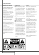
Safety Information Important Safety Information Verify Line Voltage Before Use Your AVR has been designed for use with 220240-Volt AC current. Connection to a line voltage other than that for which it is intended can create a safety and fire hazard and may damage the unit. If you have any questions about the voltage requirements for your specific model, or about the line voltage in your area, contact your dealer before plugging the unit into a wall outlet.
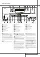
Front Panel Controls 1 Main Power Switch 2 System Power Control 3 Power Indicator 4 Headphone Jack 5 Surround Mode Group Selector 6 Speaker Select Button 7 Selector Buttons 8 Tone Mode 9 Surround Mode Selector ) Tuning ! Tuner Band Selector @ Set Button # Preset Stations Selector $ Speaker/Channel Input Indicator % Input Source Selector ^ RDS Select Button & Delay * Digital Optical 3 Input ( Surround Mode Indicators Ó Digital Coax 3 Input Ô Video 4 input jacks Input Indicators Ò Main Information Displa
Front Panel Controls 7 Selector Buttons: When you are establishing the AVR’s configuration settings, use these buttons to select from the choices available, as shown in the Main Information Display Ò. 8 Tone Mode: Pressing this button enables or disables the Balance, Bass and Treble tone controls. When the button is pressed so that the words TONE I N appear in the Main Information Display Ò, the settings of the Bass and Treble controls and of the Balance control will affect the output signals.
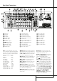
Rear Panel Connections AM Antenna FM Antenna Tape Inputs Tape Outputs Subwoofer Output DVD Audio Inputs CD Inputs Video 1 Audio Outputs DMP Connector 8-Channel Direct Inputs Digital Audio Outputs Video Monitor Outputs DVD Video Inputs NOTE: To assist in making the correct connections for multichannel input/output and speaker connections, all connection jacks and terminals have been color coded in conformance with the latest CEA standards as follows: Front Left:
Rear Panel Connections 8-Channel Direct Inputs: These jacks are used for connection to source devices such as DVD-Audio or SACD players with discrete analog outputs. Depending on the source device in use, all eight jacks may be used, though in many cases only connections to the front left/right, center, surround left/right and LFE (subwoofer input) jacks will be used for standard 5.1 audio signals.
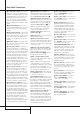
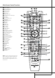
Main Remote Control Functions 0 1 2 3 4 5 6 7 8 9 A B C D E F G H I J K L M N O P Q Power Off Button IR Transmitter Window Program Indicator Power On Button Input Selectors AVR Selector AM/FM Tuner Select 6-Channel/8-Channel Direct Input Test Button Sleep Button Surround Mode Selector Night Mode Channel Select Button ⁄ / ¤ Buttons ‹ Button Set Button Digital Select Numeric Keys Tuner Mode Direct Button Tuning Up/Down OSD Button Dolby Mode Select Button DTS Digital Mode Selector Logic
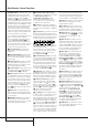
Main Remote Control Functions IMPORTANT NOTE: The AVR 240’s remote may be programmed to control up to seven devices, including the AVR. Before using the remote, it is important to remember to press the Input Selector button 4 that corresponds to the unit you wish to operate. In addition, the AVR’s remote is shipped from the factory to operate the AVR and most Harman Kardon CD or DVD players and cassette decks.
Main Remote Control Functions M Dolby Mode Selector: This button is used to select one of the available Dolby Surround processing modes. Each press of this button will select one of the Dolby Pro Logic II modes, Dolby 3 Stereo or Dolby Digital. Note that the Dolby Digital mode is only available with a digital input selected and the other modes only as long as a Dolby Digital source is not playing (except Pro Logic II with Dolby Digital 2.0 recordings, see page 31).
Installation and Connections After unpacking the unit, and placing it on a solid surface capable of supporting its weight, you will need to make the connections to your audio and video equipment. Audio Equipment Connections We recommend that you use high-quality interconnect cables when making connections to source equipment and recorders to preserve the integrity of the signals.
Installation and Connections 2. Although any video device may be connected to these jacks, we recommend connecting your video recorder to the Audio 1 Audio/Video Input Jacks so that you may take advantage of the fact that the remote control is preprogrammed with video recorder product codes for the Video 1 device.
Installation and Connections Black Figure 1: SCART/Cinch-Adapter for playback; signal flow: SCART → Cinch Yellow Red Black Red Blue1 Yellow Figure 2: SCART/Cinch-Adapter for record and playback; signal flow: SCART ↔ Cinch Green1 White Black Figure 3: Cinch/SCART-Adapter for playback; signal flow: Cinch → SCART Yellow Red Red Figure 4: SCART/S-Video Adapter for playback; signal flow: SCART → Cinch Black S-Video In Black Red Blue1 Yellow Figure 5: SCART/S-Video Adapter for record and playback; signa
Installation and Connections Speaker Selection No matter which type or brand of speakers is used, the same model or brand of speaker should be used for the front-left, center and front-right speakers. This creates a seamless front soundstage and eliminates the possibility of distracting sonic disturbances that occur when a sound moves across mismatched front-channel speakers.
System Configuration Once the speakers have been placed in the room and connected, the remaining steps are to program the system configuration memories. With the AVR two kind of memories are used, those associated individually with the input selected, e.g. surround modes, and others working globally for all inputs selected like speaker output levels, crossover frequencies or delay times used by the surround sound processor.
System Configuration However, we recommend that the first time you use the AVR, you take advantage of the simplicity of configuring the system using the EzSet+ process, which takes the guesswork out of speaker size and delay settings, and balances the speaker output levels to tailor the AVR’s sound presentation to your specific system and room. Before beginning the EzSet+ procedure, there are a few adjustments that need to be made to ensure accurate results.
System Configuration Some digital video input sources, such as a cable box or HDTV set-top may change between analog and digital outputs, depending on which channel is in use. The AVR’s Auto Polling feature allows you to avoid losing the audio feed when this happens by permitting both analog and digital connections to the same source on the AVR. Digital audio is the default, and the unit will automatically switch to the analog audio if the digital audio stream stops.
System Configuration To select the mode that will be used as the initial default for an input, first press the ⁄/¤ buttons D until the on-screen cursor is next to the desired mode’s master category name. Next, press the Set Button F to view the sub-menu. Press the ‹/› Buttons E to scroll through the available choices, and then press the ¤ Button D so that the cursor is next to BACK TO MASTER MENU to continue the setup process.
System Configuration When a DTS source is playing, the choice of modes for 7.1 systems will vary according to the type of program source (DTS Stereo, DTS 5.1, DTS-ES Matrix or DTS-ES Discrete). Press the ‹/› Buttons E to scroll through the choices that are available for your system and the program in use. With no source playing, or while an analog audio source is playing, you will only be able to view the DTS Neo:6 surround mode choices.
System Configuration need for manual adjustment of speaker “size”, crossover, delay and output level settings. With EzSet+ your new receiver even alerts you to errors in speaker connections that prevent a speaker from functioning. With EzSet+ you are able to calibrate your system in a fraction of the time it would take to enter the settings manually, and with results that rival those achieved with expensive test equipment and time-consuming procedures.
System Configuration NOTE: While this test detects whether a speaker is connected to a particular output, it cannot determine whether the speaker is in the correct position. (For example, it can tell whether a speaker is connected to the Surround Right output, but it cannot tell whether the speaker is on the right or left side of your listening room.) For that reason, we strongly recommend that you try to listen as the tone circulates, matching the name shown for each channel to the location of the speaker.
System Configuration The first line of the MANUAL SETUP menu indicates whether EzSet+ has been run and its settings saved. If this line indicates Y E S, then you will be able to see the settings determined by EzSet+ as you view the SPEAKER S I Z E, SPEAKER X O V E R, DELAY ADJUST and CHANNEL ADJUST submenus.
System Configuration NOTE: When the front speakers are set to the LARGE option and the surround mode is set to "Surround Off", or pure two-channel stereo, when an analog signal source is present it will be routed directly from the input to the volume control without being digitized or processed. If you have full-range front speakers and wish to remove all digital processing from the circuit path, select this configuration.
System Configuration subwoofer will receive the front left and right bass frequencies under the crossover frequency selected in another setting on this menu, as described below, and also the LFE soundtrack. 9. When all initial speaker “size” settings have been made, you now have the option to take advantage of the AVR’s Quadruple Crossover system, which allows individual crossover settings to be made for each speaker group.
System Configuration Delay Settings Due the different distances between the listening position for the front channel speakers and the surround speakers, the amount of time it takes for sound to reach your ears from the front or surround speakers is different. You may compensate for this difference through the use of the delay settings to adjust the timing for the specific speaker placement and acoustic conditions in your listening room or home theater.
System Configuration setting. The ⁄/¤ Navigation Button D may be used to select another position, or you may simply wait five seconds for the system to time out and return to normal operation. The delay settings may be adjusted at any time using the remote control and while viewing an on-screen image by pressing the Delay Select Button .
System Configuration NOTE: Remember that when your system has only a single Surround Back speaker and is thus configured for 6.1-channel operation, you will hear the test tone twice from the back speaker, once with the SBL indication and once with the SBR indication. This is normal, and it allows you to adjust the output balance for the mixing circuit that creates a 6.1 output when 7.1 modes such as Logic 7/7.1 are used. 6.
System Configuration Once the settings outlined on the previous pages have been made, the AVR is ready for operation. While there are some additional settings to be made, these are best done after you have had an opportunity to listen to a variety of sources and different kinds of program material. These advanced settings are described on pages 37 to 38 of this manual. In addition, any of the settings made in the initial configuration of the unit may be changed at any time.
Operation Surround Mode Chart MODE FEATURES DOLBY DIGITAL Available only with digital input sources encoded with Dolby Digital data. It provides up to five separate main audio channels and a special dedicated Low Frequency Effects channel. DOLBY DIGITAL EX Available when the receiver is configured for 6.1/7.1 channel operation, Dolby Digital EX is the latest version of Dolby Digital.
Operation Surround Mode Chart MODE FEATURES DTS Neo:6 Cinema DTS Neo:6 Music These two modes are available when any analog source is playing to create a six-channel surround presentation from conventional Matrix-encoded and traditional Stereo sources. Select the Cinema version of Neo:6 when a program with any type of analog Matrix surround encoding is present. Select the Music version of Neo:6 for optimal processing when a nonencoded, two-channel stereo program is being played.
Operation Basic Operation Once you have completed the setup and configuration of the AVR, it is simple to operate and enjoy. The following instructions should be followed for you to maximize your enjoyment of your new receiver: Turning the AVR On or Off • When using the AVR for the first time, you must press the Main Power Switch 1 on the front panel to turn the unit on. This places the unit in a Standby mode, as indicated by the amber color of the Power Indicator 3.
Operation • To set the output of the AVR so that the output is “flat,” with the tone and balance controls deactivated, press the Tone Mode button 8 once or twice so that the words Tone Off appear momentarily in the Main Information Display Ò. To return the tone controls to an active condition, press the Tone Mode 8 button once or twice so that the words Tone I n momentarily appear in the Main Information Display Ò. • For private listening, plug the 6.
Operation DTS DTS is another digital audio system that is capable of delivering 5.1, 6.1 or 7.1 audio. Although both DTS and Dolby Digital are digital, they use different methods of encoding the signals, and thus they require different decoding circuits to convert the digital signals back to analog. DTS-encoded sound tracks are available on select DVD and LD discs, as well as on special audioonly DTS CDs.
Operation An UNLOCK message may appear in the Lower Display Line Ò. This is your indication that the digital audio data stream has been interrupted or is no longer present. When that occurs, the unit’s digital signal processor has no signal to lock onto, and is thus “unlocked.
Operation back speakers may light (when those speakers have been configured) to indicate that a signal will be fed to them (Matrix decoded with NEO:6, LOGIC 7 or 7 CH Stereo), but no letters inside will light as the unit will not receive an input signal for the surround back channels. guide that accompanies the DVD or laser disc to determine which type of audio has been recorded on the disc.
Operation Advanced Features Once the reference level has been set, press the Channel Select button CÙ and note that FRONT L LEVEL will appear in the Main Information Display Ò. To change the level, first press the Set button F @, and then use the Selector buttons 7 or the ⁄/ ¤ buttons D to raise or lower the level. DO NOT use the volume control, as this will alter the reference setting.
Advanced Features Turn On Volume Level Semi-OSD Settings Full-OSD Time Out Adjustment As is the case with most audio/video receivers, when the AVR is turned on, it will always return to the volume setting in effect when the unit was turned off. However, you may prefer to always have the AVR turn on at a specific setting, regardless of what was last in use when the unit was turned off.
Tuner Operation Default Surround Mode In normal operation, when the AVR senses a Dolby Digital or DTS digital audio data stream, it will automatically switch the appropriate default surround mode, with the AVR responding to the data flags that are encoded on the DVD disc or in the digital video broadcast. In most cases, this is the correct mode, but you may have a particular preference for the mode you wish to hear when Dolby Digital or DTS is present.
Tuner Operation RDS Operation The AVR 240 is equipped with RDS (Radio Data System), which brings a wide range of information to FM radio. Now in use in many countries, RDS is a system for transmitting station call signs or network information, a description of station program type, text messages about the station or specifics of a musical selection, and the correct time.
Programming the Remote The AVR 240 is equipped with a powerful remote control that will control not only the receiver’s functions, but also most popular brands of audio and video equipment, including CD players, TV sets, cable boxes, VCRs, satellite receivers and other home-theater equipment. Once the AVR’s remote is programmed with the codes for the products you own, it is possible to eliminate most other remotes and replace them with the convenience of a single universal remote control.
Programming the Remote Example: One blink, followed by a one-second pause, followed by six blinks, followed by a onesecond pause, followed by four blinks indicates that the code has been set to 164.
Programming the Remote To program the remote for Volume PunchThrough, follow these steps: 1. Press the Input Selector 4 for the unit you wish to have associated with the volume control at the same time until and the Mute button the red light illuminates under the Input Selector 4 and note that the Program Indicator 2 will flash amber. 2. Press the Volume Up button and note that the Program Indicator 2 will stop flashing and stay amber. 3.
Function List 44 FUNCTION LIST No. Button Name AVR Function DVD CD/CDR 1 2 3 4 5 6 7 8 9 10 11 12 13 14 15 16 17 18 19 20 21 22 23 24 25 26 27 28 29 30 31 32 33 34 35 36 37 38 39 40 41 42 43 44 45 46 47 48 49 50 51 52 53 54 55 56 57 58 59 60 61 62 63 64 65 66 67 68 69 Power On Power Off Mute AVR DVD CD Tape VID 1 VID 2 VID 3 VID 4 DIM AM/FM 6/8 Ch.
Function List No. Button Name Tape VCR (VID 1) TV (VID 3) CBL (VID 2) SAT (VID 2) 1 2 3 4 5 6 7 8 9 10 11 12 13 14 15 16 17 18 19 20 21 22 23 24 25 26 27 28 29 30 31 32 33 34 35 36 37 38 39 40 41 42 43 44 45 46 47 48 49 50 51 52 53 54 55 56 57 58 59 60 61 62 63 64 65 66 67 68 69 Power On Power Off Mute AVR DVD CD Tape VID 1 VID 2 VID 3 VID 4 DIM AM/FM 6/8 Ch.
Troubleshooting Guide SYMPTOM CAUSE SOLUTION Unit does not function when Main Power Switch 1 is pushed • No AC Power • Make certain AC power cord is plugged into a live outlet • Check to see if outlet is switch controlled Display lights, but no sound or picture • Intermittent input connections • Make certain that all input and speaker connections are secure • Press Mute button • Turn up volume control • Mute is on • Volume control is down No sound from any speaker; light around Power switch 2 is re
Technical Specifications Audio Section Stereo Mode Continuous Average Power (FTC) 65 Watts per channel, 20Hz–20kHz, @ < 0.07% THD, both channels driven into 8 ohms 7 Channel Surround Modes Power Per Individual Channel Front L&R channels: 50 Watts per channel, @ < 0.07% THD, 20Hz–20kHz into 8 ohms Center channel: 50 Watts, @ < 0.07% THD, 20Hz–20kHz into 8 ohms Surround (L & R Side, Back) channels: 50 Watts per channel, @ < 0.
APPENDIX – SETTINGS WORKSHEET Table 1: Input Settings FEATURE DVD VIDEO 1 VIDEO 2 VIDEO 3 VIDEO 4 CD TAPE TUNER DMP Input Title Component Video Input Component Component Component Component Video 1 Video2 Video 2 Video 2 (Y/N) (Y/N) (Y/N) (Y/N) 6/8 CH.
INTRODUCTION 49
250 Crossways Park Drive, Woodbury, New York 11797 www.harmankardon.com Harman Consumer Group International: 2, route de Tours, 72500 Château-du-Loir, France © 2005 Harman Kardon, Incorporated Part No.