Owner's Manual with Assembly Instructions For Model M0412 ® Please read this manual and save it with your original sales receipt. Tools needed for assembly: Phillips Screwdriver, Hammer and Safety Scissors (all not included). Use only with a Power Wheels® 12 Volt Rechargeable Battery and Power Wheels® 12 Volt Charger with Type 12V Connector (both included). Cruiser Product features may vary from the picture above.
A TABLE OF CONTENTS A Important Information . . . . . . . . . . . . . . . . . . . . . . . . . . . . . . . . . . . . . . . . . . . . . . . . . . . . . . . . . . . . . . . . . . . . . . . . . . . . . . . . . . . .2 B Warnings and Cautions . . . . . . . . . . . . . . . . . . . . . . . . . . . . . . . . . . . . . . . . . . . . . . . . . . . . . . . . . . . . . . . . . . . . . . . . . . . . . . . . . . .3 C Parts . . . . . . . . . . . . . . . . . . . . . . . . . . . . . . . . . . . . . . . . . . . . . . . . . .
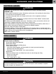
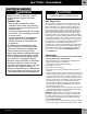
WARNINGS AND CAUTIONS B ELECTRICAL HAZARD WARNING • Battery can fall out and injure a child if vehicle tips over. Always use battery retainer. • PREVENT FIRE - Never modify the electrical system. Alterations could cause a fire resulting in serious injury and could also ruin the electrical system. - Use of the wrong type battery or charger could cause a fire or explosion resulting in serious injury.
PARTS C • If you experience a problem with this product, or are missing a part, please call us at 1-800-348-0751, rather than return this product to the store. • Please identify all parts before assembly and save all packaging material until assembly is complete to ensure that no parts are discarded. • Metal parts have been coated with a lubricant to protect them during shipment. Wipe all metal parts with a paper towel to remove any excess lubricant.
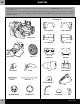
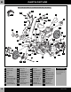
TABLE PARTS OF CONTENTS A Right Handlebar Left Handlebar Mirror Clamp Hex Bushing - 2 C Long Hex Bushing - 2 Mirror Lens - 2 Handgrips - 2 Axle Bushing - 2 Handlebar Harness 12 Volt Battery Left Mirror Left Shock Set Outer Inner Tachometer Cover 12 Volt Charger Right Mirror Right Shock Set Inner Outer Air Cleaner Cover .354" .437" .354 Cap Nut - 2 .
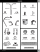
TABLE PARTS OF PICTURE CONTENTS D A Note: Some parts shown are assembled on both sides of the vehicle.
BATTERY CHARGING E ELECTRICAL HAZARD WARNING • Battery can fall out and injure a child if vehicle tips over. Always use battery retainer. • PREVENT FIRE - Never modify the electrical system. Alterations could cause a fire resulting in serious injury and could also ruin the electrical system. - Use of the wrong type battery or charger could cause a fire or explosion resulting in serious injury.
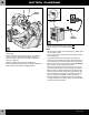
BATTERY CHARGING E Battery Retainer B 12V Battery Battery A Charger Connector 2 1 • Loosen the two screws holding the battery retainer to the vehicle body. • Remove the screws and the battery retainer. Set the battery retainer and screws aside. Do not throw out the battery retainer or screws. You will use them when installing your battery (see page 24). • Remove the battery from the battery compartment.
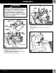
ASSEMBLY F WARNING Vehicle Frame Children can be harmed by small parts, sharp edges and sharp points in the vehicle's unassembled state, or by electrical items. Care should be taken in unpacking and assembly of the vehicle. Children should not handle parts, including the battery, or help in assembly of the vehicle. Large Rectangular Opening 2 Vehicle Body Square Opening Vehicle Body High Speed Hook-Up • Insert four #8 x 3/4" screws through the vehicle body and into the vehicle frame.
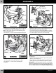
ASSEMBLY F Peg Right Exhaust Pipe - Inner Half Vehicle Body Hole Tab Left Footboard Stabilizer Wheel Slots 4 Tab Left Side View 6 • Fit the tabs on the left footboard into the slots in the left side of the vehicle frame. Make sure both tabs are in the slots. Hint: You may need to squeeze the left footboard in order to align the tabs with the slots. • Insert two #8 x 3/ 4" screws into the left footboard and tighten. Vehicle Frame (Right Side) • Separate the exhaust set pieces.
ASSEMBLY Right Exhaust Pipe - Outer Half F .437" Wheel Axle .437 (Large Diameter) Cap Nut 8 • Fit the outer half of the right exhaust pipe (R) to the inner half of the right exhaust pipe. 11 • Separate the fork axle from the two wheel axles. (The fork axle is shorter than the wheels axles.) Set the fork axle aside for assembly step 33. • Place a .437 (large diameter) cap nut on a flat surface, inside up. • Fit the end of a wheel axle into the cap nut.
ASSEMBLY F Saddlebag Notch Axle Bushing Tab Groove Rear Fork Arm Rear Fork Arm Wheel (with Hex Bushings) 14 16 Back View • Position the vehicle assembly so that the back is facing you. • While holding the hex bushings in place, position the wheel between the rear fork arms of the vehicle frame. • Slide the wheel axle (with axle bushing) through one rear fork arm, through the wheel (with hex bushings) and out through the other rear fork arm.
ASSEMBLY F Headlight Lens Front Fork Assembly Headlight Assembly Headlight Housing Center Holes 20 18 • Fit the headlight lens onto the headlight housing. • Insert three #8 x 3/4" screws into the headlight lens and tighten. • Position the headlight assembly with the lens down on a flat surface. • Fit the front fork assembly onto the back of the headlight assembly, as shown. • Insert two #8 x ¾" screws through the center holes in the front fork assembly and into the headlight assembly.
ASSEMBLY F Switch Cover Right Handlebar Peg Switch Grip Area Additional Hole 24 22 Right Handlebar • Locate the right handlebar. The right handlebar has an additional hole in the grip area. • Fit the switch to the right handlebar, making sure the screw hole in the switch aligns with the screw hole in the right handlebar. • Fit the peg on the right mirror through the hole in the right handlebar and the switch.
ASSEMBLY F Front Fork Assembly Handlebar Harness Upper Hole in Front Fork DO NOT insert the plug through the lower hole in the front fork! Plug End of Wire Cover Fork Cover 28 Back View • Turn the front fork assembly around so the back is facing you. • Slide the end of the wire cover into the upper hole in the front fork, as shown. 26 Upper Hole Front View • Position the front fork so that it is upright and facing you.
ASSEMBLY F Front View Handlebar Harness B A TM Handlebar Harness See Inset Handlebars 30 • Align the screw holes in each handlebar with the screw holes in the front fork. • First, insert two #8 x ¾" screws through the lower holes in the front fork and into each lower hole in each handlebar A and hand tighten. Do not tighten the screws completely. These screws will be tightened in step 50.
ASSEMBLY F .354 (Small Diameter) Cap Nut Neck of Vehicle Body .354" B TM TM A 34 Steering Stop Handlebar Assembly • First, fit the tab on the steering stop into the curved slot in the lower steering bushing A . • Hold the steering stop in place. • Then, slide the handlebar assembly on the vehicle frame neck and over the steering stop B . .
ASSEMBLY F F PUSH HERE Tank Seat Tab Seat Tab Tabs Slot TM Right Side View 38 • Balance the sound box on the vehicle body. (The speaker should face down.) • Fit the tabs at the bottom of the tank under the front end of the vehicle body. • Lower the tank on the vehicle frame, making sure that the two small square openings in the tank fit over the buttons on the sound box. 40 • Fit the tab on the front of the seat into the slot near the tank.
ASSEMBLY F Tachometer Inner Right Shock Inner Left Shock Fork Cover Outer Left Shock Outer Right Shock 44 TM 42 • Fit the tachometer to the fork cover. • Insert two #8 x ¾" screws into the tachometer and tighten. Front Fork Tabs Handlebar • The shock sets may be held together by rubber bands to aid in assembly. After completing assembly step 44, remove and throw away the rubber bands. • Fit the inner and outer left shock halves together (they are labeled on the inside with an “L”).
ASSEMBLY ASSEMBLY F Wheel 18 Guide Guide Guide 18 Guide 20 F 20 Wheel Axle 21 21 19 19 Shock Shock Front Wheel 46 Wheel (with Long Hex Bushings) 48 • Before applying labels to the front wheel, wipe the wheel with a clean, dry cloth to remove any dust or oils. • Apply labels to both sides of the front wheel as shown in the illustration. IMPORTANT! Labels 18 and 19 are designed to slightly overlap; and labels 20 and 21 are designed to slightly overlap.
ASSEMBLY Tighten Screws F Tighten Screws Primary Cover 50 • Now, completely tighten the four screws in the front handlebar assembly to secure the handlebars. Left Mirror Mirror Clamp 53 • Fit the primary cover onto the left side of the vehicle, as shown. • Insert two #8 x 3/4" screws through the primary cover and into the vehicle frame. Tighten the screws. Right Side View Handlebar 51 Air Cleaner Cover Air Cleaner • Fit the left mirror to the left handlebar.
TABLE DECORATION OF CONTENTS G A Proper label application will help to keep the labels looking their best! When applying labels, keep the following guidelines in mind: • Wash your hands before applying the labels. • Before applying the labels, wipe the surface of the vehicle with a clean, dry cloth to remove any dust or oils. • Place the labels exactly as shown in the illustrations. • For best results, avoid repositioning a label once it has been applied to the vehicle.
DECORATION G 17 8 22 8 11 5 5 TM 14 30 32 12 32 RIGHT SIDE 12 8 23 8 5 11 5 TM 16 ® 33 15 32 LEFT SIDE M0412a-0920 12 32 12 23
BATTERY INSTALLATION H IMPORTANT! Use only a Power Wheels® 12 volt lead-acid rechargeable battery. Use of any other battery will damage your vehicle. Make sure that you charge the battery for at least 18 hours using the enclosed Power Wheels® 12 volt charger before operating your vehicle for the first time. Charge the battery for at least 14 hours after each use of the vehicle. Never charge the battery longer than 30 hours.
BATTERY CARE AND DISPOSAL Care If a battery leak develops, avoid contact with the leaking acid and place the damaged battery in a plastic bag. See information below for proper disposal. If acid comes in contact with skin or eyes, flush with cool water for at least 15 minutes and call a physician. If acid is internally ingested, give water, milk of magnesia or egg whites immediately. Never give emetics or induce vomiting. Call a physician. • Charge a new battery for at least 18 hours before first use.
SAFE DRIVING RULES J RIDING HAZARD WARNING • Prevent Injuries and Deaths • Direct Adult Supervision Required • Never Ride at Night. • Keep Children Within Safe Riding Areas. These areas must be: - away from swimming pools and other bodies of water to prevent drownings - generally level to prevent tipovers - away from steps, steep inclines, cars, roads and alleys. • Riding Rules Make sure children know and follow these rules for safe driving and riding. - Always sit on the seat. - Always wear shoes.
VEHICLE OPERATION K IMPORTANT! Use this vehicle ONLY outdoors. Most interior flooring can be damaged by riding this vehicle indoors. Fisher-Price® will not be responsible for damage to the floor if the vehicle is used indoors. Beginner Use - Low Speed Drive IMPORTANT! As assembled, your vehicle is ready to roll in low speed (21/2 mph, maximum).
L VEHICLE CARE • Check all screws, cap nuts and their protective coverings regularly and tighten as required. Check plastic parts on a regular basis for cracks or broken pieces. • During snowy or rainy weather, the vehicle should be stored inside or under a protective cover. Remember to charge the battery at least once per month while your vehicle is not in regular use. • Avoid operating the vehicle in wet or snowy conditions, and do not spray the vehicle with a hose.
PROBLEMS AND SOLUTIONS GUIDE N IMPORTANT! If you experience a problem with your vehicle, first check the Problems and Solutions Guide below. If you still experience a problem, please contact Power Wheels® Consumer Relations, toll-free at 1-800-348-0751 between 9 AM and 7 PM (EST) Monday through Friday or 11 AM and 5 PM (EST) Saturday. Or, contact your local Power Wheels® authorized service center. For the location nearest you, please visit us on-line at www.powerwheels.com, or call 1-800-348-0751.
N PROBLEMS AND SOLUTIONS GUIDE PROBLEM Vehicle was running but suddenly stopped Short run time (Less than 1 - 3 hours per charge) POSSIBLE CAUSE SOLUTION Loose wires or loose connectors Check all wires and connectors. Make sure the motor harness connector is tightly plugged into the battery, and that there are no loose wires around the motors.
PROBLEMS AND SOLUTIONS GUIDE PROBLEM Vehicle runs sluggishly POSSIBLE CAUSE Undercharged battery N SOLUTION Charge the battery. A new battery should have been charged for at least 18 hours before using the vehicle for the first time. After first-time use, recharge the battery for at least 14 hours after each use. Never charge the battery longer than 30 hours. Check all connectors. Make sure the charger connector is tightly plugged into the battery connector, and that the charger is plugged into the wall.
Before first-time use, you must charge the battery 18 hours! Charge the battery immediately after each use. Charge the battery once a month, even if the vehicle is not used or stored. Do not return your vehicle to the store! Or contact your local independently owned and operated Power Wheels® Authorized Service Center. For the location nearest you, visit us on-line at www.powerwheels.com. Harley-Davidson and the Harley-Davidson Bar & Shield logo are registered trademarks of H-D Michigan, Inc.