
User guide

ADVANTAGE LITE SERIES: HI LPRE
INSTALLATION AND ASSEMBLY INSTRUCTIONS
Model Numbers
CAPACITY
Load Point
Model Number
Load Sensor
Model Number
LB KG
440 200 HI LPRE440-33C HI SB02-440
1100 500 HI LPRE1.1K-33C HI SB02-1.1K
2200 1000 HI LPRE2.2K-33C HI SB02-2.2K
4400 2000 HI LPRE4.4K-33C HI SB02-4.4K
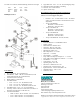
Basic Engineering Principle for Positioning Load Point
Assemblies
• Load Point Assemblies should be positioned such that the
load (weight) is distributed as evenly as possible between
each load point assembly in the scale.
Site Preparation
• All foundations for the HI LPRE load point assemblies
require a metal base plate adequate to prevent any deforma-
tion of the plate when welding the base or spacer of the load
point assembly to the foundation.
• All mounting surfaces for the base and loading plate must be
level. The Load Point Assemblies in a system must be level
to within ± 0.5
o
.
• Welding should be done prior to the installation of the load
sensor. Otherwise disconnect load sensor wiring from the
instrument and bypass each load sensor with heavy ground
strap from live weight side of each load point to earth
ground.
Precautions
• Always treat the Load Sensor as a precision instrument.
Leave the assembly in its packaging until it is time for instal-
lation.
• NEVER CARRY OR SWING THE LOAD SENSORS
BY THEIR CABLE.
• Never allow moisture to get into any interconnections.
• Keep the Load Point Assembly free of debris.
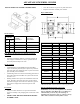
Physical Dimensions
MODEL # A B C
HI LPRE440-33C 6.13 (155.8) 3.15 (80.0) 3.27 (83.0)
HI LPRE1.1K-33C 6.13 (155.8) 3.15 (80.0) 3.27 (83.0)
HI LPRE2.2K-33C 6.13 (155.8) 3.15 (80.0) 3.27 (83.0)
HI LPRE4.4K-33C 6.13 (155.8) 3.15 (80.0) 3.27 (83.0)
MODEL # D E F
HI LPRE440-33C 4.22 (107.1) 2.28 (58.0) 2.52 (64.0)
HI LPRE1.1K-33C 4.22 (107.1) 2.28 (58.0) 2.52 (64.0)
HI LPRE2.2K-33C 4.22 (107.1) 2.28 (58.0) 2.52 (64.0)
HI LPRE4.4K-33C 4.22 (107.1) 2.28 (58.0) 2.52 (64.0)
MODEL # G H Height*
HI LPRE440-33C 2.12 (53.9) 1.44 (36.5) 3.37 (54.7)
HI LPRE1.1K-33C 2.12 (53.9) 1.44 (36.5) 3.37 (54.7)
HI LPRE2.2K-33C 2.12 (53.9) 1.44 (36.5) 3.63 (92.1)
HI LPRE4.4K-33C 2.12 (53.9) 1.44 (36.5) 4.59 (116.6)
* Measured from the bottom of the base to the top plate bolts.
Electrical Termination Cable Color Codes
WARNING: Load cell cable length has been calculated
into C2 calibration data. Hardy Process Solutions rec-
ommends that you do not cut your Advantage or
Advantage Lite load sensor cable, as your C2 accuracy
will be affected and the warranty will be voided.