
Product manual


SCROLL BENDING
Once you have become completely familiar with the assembly and operations manuals, you
will be able to assemble your Compact Bender. If you wish to proceed to bending wrought
iron stock into various scrolls, you will need to assemble the Compact Bender and the Scroll
Bending Attachment that is intended to be used with the Compact Bender.
The Scroll Bending Attachment is designed for bending 3/16” x 1/2” up to 3/16” x 1” hot rolled
mild flat wrought iron stock. You can purchase this stock at most home improvement centers.
Please note: The Scroll Bending Attachment is not recommended for bending 1/8” thick
material.
The Bushing, (#S03) described on page 5 of the Scroll Bending Attachment manual, keeps the
scroll flat as it is formed. If you wish to make several scrolls of the same size, you will need
to draw a chalk mark on the stock to indicate how far you should bend before stopping. Stop
bending the stock at the point where the stock just touches the attachment. If each successive
scroll is bent until the pre-measured chalk mark on the stock just touches the attachment, the
scrolls will be of similar size. To keep the scrolls as uniform as possible, be sure the stock
remains rested on the bottom flange of the roller bushing during all scroll bending operations.
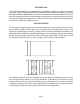
Please note: Always begin the scroll by placing the pin and bushing into hole #3. When
making larger scrolls you will need to move the pin and the roller bushing out to accommodate
the length of the stock.
Hole #6
Hole #3
When making scrolls, the STOCK LENGTH refers to the length to cut the stock. The CHALK
MARK refers to the distance from one end of the material to a chalk mark which you draw on
the stock. When bending scrolls, insert the end farthest from the chalk mark into the Scroll
Bending Attachment. When two scrolls are to be bent from the same piece of material, two
chalk mark distances are indicated in the sample tables. One chalk mark should be measured
from one end of the stock, and the other chalk mark should be measured from the other end
as illustrated on the following page.
Page 3