® COMBO RATCHET/IMPACT SET Assembly and Operating Instructions ® 3491 Mission Oaks Blvd. / Camarillo, CA 93011 Copyright © 1997 by Harbor Freight Tools®. All rights reserved. No portion of this manual or any artwork contained herein may be reproduced in any shape or form without the express written consent of Harbor Freight Tools. For technical questions and replacement parts, please call 1-800-444-3353.
SPECIFICATIONS RATCHET WRENCH Average Air Consumption Recommended Air Pressure Air Inlet Free Speed Maximum Torque (ft. lbs.) IMPACT WRENCH Bolt Capacity Speed Air Inlet Sockets Maximum Torque (ft. lbs.) — 4 CFM 90 PSI ¼” NPT 150 RPM 45 — 1/2" 7000 RPM ¼” NPT 7/16" – 1" 230 SAVE THIS MANUAL You will need the manual for the safety warnings and cautions, assembly instructions, operating procedures, maintenance procedures, trouble shooting, parts list, and diagram. Keep your invoice with this manual.
6. USE THE RIGHT TOOL FOR THE JOB. Do not attempt to force a small tool or attachment to do the work of a larger industrial tool. Do not use a tool for a purpose for which it was not intended. 7. DRESS PROPERLY. Do not wear loose clothing or jewelry as they can be caught in moving parts. Non-skid footwear is recommended. Wear restrictive hair covering to contain long hair. 8. USE EYE AND EAR PROTECTION. Always wear ANSI-approved chemical splash goggles when working with chemicals.
18. DRAIN COMPRESSOR EVERY DAY. Do not allow moisture to build up inside the compressor. Do not allow compressor to sit pressurized for longer than one hour. 19. MAKE SURE ALL EQUIPMENT IS RATED TO THE APPROPRIATE CAPACITY. Make sure that the regulator is set at least 10 PSI lower than the lowest rated piece of equipment you are using. 20. DO NOT USE OXYGEN, COMBUSTIBLE GASES, OR BOTTLED GASES AS A POWER SOURCE. The tool may explode, possibly causing injury. 21.
GROUNDING INSTRUCTIONS If compressor has a three-prong plug 1. This machine has a three-prong plug. The third prong (round) is the ground. Plug the machine’s cord only into three-prong receptacles. Never cut off the round prong. Cutting off the ground will result in a safety hazard and void the warranty. 2. If a three-prong receptacle is not available, you may use an adapter.
UNPACKING When unpacking, check to make sure the following parts are included. All sizes listed below are approximate. If any parts are missing or broken, please call Harbor Freight Tools at the number on the cover of this manual. Item# N/A N/A N/A N/A Description 3/8" Ratchet Wrench 1/2" Impact Wrench 3/8" to 1/2" Adapter 4mm Hex Wrench Item# N/A N/A N/A Description Impact Sockets (7/16" – 1") Oil Pot Air Coupler ASSEMBLY Your Air Ratchet comes completely assembled.
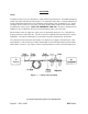
OPERATION Setup Frequent, but not excessive, lubrication is required for best performance. Oil added through the airline connection will lubricate internal parts. An automatic airline oiler is recommended but oil may be added manually before every operation or after about 1 hour of continuous use. Only a few drops of oil at a time are necessary. Too much oil will collect inside the tool and be blown out during the exhaust cycle. ONLY USE PNEUMATIC TOOL OIL.
Air Ratchet Operation Step 1: Select the appropriate socket for your needs. Step 2: Attach the socket to the RATCHET ANVIL (#18) as shown in Figure 2. 123456 123456 123456 123456 123456 123456 123456 123456 123456 123456 Air Inlet Roll Pin (#5) Figure 2 — Attaching the Socket Step 3: Set the compressor’s pressure regulator to 90 PSI. Do not set the compressor’s outlet regulator over 90 PSI. Step 4: Connect the Air Ratchet to the air compressor’s hose.
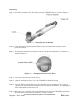
Loosening Step 1: Check the direction of the drive by pressing the TRIGGER (#4) as shown in Figure 3. 1234567 1234567 1234567 123456 1234567 123456 1234567 123456 123456 123456 123456 Figure 3 — Operating the Air Ratchet Step 2: If the Air Ratchet is going counterclockwise (the correct direction to loosen), then proceed to Step 4. Step 3: To change the direction of the drive to loosen, turn the dial marked “R-F” clockwise as shown in Figure 4.
Tightening Step 1: Check the direction of the drive by pressing the TRIGGER (#4) as shown in Figure 3. Step 2: If the Air Ratchet is going clockwise (the correct direction to tighten), then proceed to Step 4. Step 3: To change the direction of the drive in order to tighten, turn the dial marked “R-F” counterclockwise as shown in Figure 5 Figure 5 — Changing the Direction of the Drive Step 4: Thread the nut on as far as you can by hand. Step 5: Place the socket on the nut.
MAINTENANCE Your Air Ratchet is best operated with an Airline Oiler. If you are using the Air Tool without an Airline Oiler, follow the steps below. Step 1: Disconnect the Air Ratchet from the air hose. Step 2: Apply a few drops of PNEUMATIC TOOL OIL through the air inlet before each use, or every hour if used continuously. CAUTION Do not use detergent oil or additives as these lubricants will cause accelerated wear to the seals in the tool.
Impact Wrench Operation Step 1: Set the compressor’s pressure regulator to a maximum of 90 PSI. 90 PSI is satisfactory without harming this tool. Step 2: Remove the plastic cap from the rear of the HOSE ADAPTER (#10). Step 3: Wrap the threads of the Air Coupler with pipe thread seal tape (not included). Attach the Air Coupler to the HOSE ADAPTER. Tighten the fitting. Step 4: Determine the socket size necessary for the job you need to do.
Step 6: Select the power setting for Loosening by pushing in and turning the AIR REGULATOR (#11) located on the bottom of the CAUTION Impact Wrench as shown in Figure 8. Use the Setting Appropriate for the When the AirRegulator is completely Job. Do Not Set the Power Setting screwed in it is at it’s lowest setting. Higher Than Needed. Damage to Air pressure increases as you push in Parts Could Result. and turn the Air Regulator.
Step 8: Press the TRIGGER (#4) to test the Impact Wrench. The Impact Wrench should spin freely as shown if Figure 10. Figure 10 — Pressing Trigger Loosening Step 1: Verify that the power level is correct for your needs and that the REVERSE VALVE (#3) has been shifted (pressed) completely to the right. If not, refer to Steps 6 through 7 under Impact Wrench Operation before proceeding. Step 2: Place your work in as clear a location as possible.
Tightening Step 1: Verify that the power level is correct for your needs and that the REVERSE VALVE (#3) has been shifted (pressed) completely to the left. If not, refer to Steps 6 through 7 under Impact Wrench Operation before proceeding. Step 2: Place your work in as clear a location as possible. Make sure the air hose will reach as far as needed without stressing any connections. Step 3: Thread the nut or bolt on as far as possible by hand. This is to prevent cross-threading.
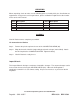
PARTS LIST – RATCHET WRENCH Item# 1 2 4 5 6 7 8 9 10 11 12 13 14 15 16 17 18 19 20 21 22 Parts No.
Exploded View Diagram - Ratchet Wrench For technical questions, please call 1-800-444-3353.
PARTS LIST – AIR IMPACT WRENCH Item# 1 2 3 4 5 6 7 8 9 10 11 12 13 14 15 16 17 18 19 20 21 22 Parts No.
Exploded View Diagram -- Air Impact Wrench For technical questions, please call 1-800-444-3353.