8 ton air/hydraulic long ram jack Model 94562 Set up and Operating Instructions Visit our website at: http://www.harborfreight.com Read this material before using this product. Failure to do so can result in serious injury. Save this manual. Copyright© 2006 by Harbor Freight Tools®. All rights reserved. No portion of this manual or any artwork contained herein may be reproduced in any shape or form without the express written consent of Harbor Freight Tools.
Specifications Lifting Capacity 8 Tons (16,000 Pounds) Ram Diameter 1.
or medication. A moment of inattention while operating power tools may result in serious personal injury. 2. Dress properly. Do not wear loose clothing or jewelry. Contain long hair. Keep your hair, clothing, and gloves away from moving parts. Loose clothes, jewelry, or long hair can be caught in moving parts. 3. Do not overreach. Keep proper footing and balance at all times. Proper footing and balance enables better control in unexpected situations. 4. Always wear eye and hand protection.
Specific Safety Rules 1. Prior to assembling the Long Ram Jack onto a shop crane, make sure to read and understand all instructions and safety precautions as outlined in the shop crane manufacturer’s manual. Make sure the Long Ram Jack is fully compatible with the shop crane. 2. WARNING! Do not exceed the maximum lifting capacity of this Long Ram Jack (8 tons / 16,000 pounds). Exceeding the maximum lifting capacity could cause personal injury and/or property damage. 3.
15. Do not attempt to move a load while it is supported by the Long Ram Jack. The Jack must only be used in a static position for lifting and lowering loads. 16. Compressed air only. Use clean, dry, regulated, compressed air between 110 and 120 PSI. Never use oxygen, carbon dioxide, combustible gases, or any other bottled gas as a power source for this product. 17. This Jack is intended for use on a shop crane (not included), properly attached.
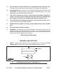
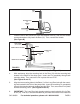
RAM (13) RELEASE VALVE (4) HANDLE (21) BASE (1) FIGURE B 2. Place the end of the Handle (21) over the Release Valve (4), and turn the Handle counterclockwise to fully lower the Ram (13). Then, remove the Handle. (See Figure B.) SHOP CRANE (NOT INCLUDED) BOOM INSERT PIN & R-PIN HERE o PILLAR FILLER PLUG (17) RESERVOIR (16) INSERT PIN & R-PIN HERE FIGURE C 3. Lower the Boom on the shop crane (not included). (See Figure C.) 4.
prior to the shop crane’s first use and, if necessary, top off the Reservoir with the proper amount of hydraulic oil. To do so, remove the Filler Plug (17) located on the Reservoir. Top off the Reservoir with hydraulic oil. Make sure the Release Valve (4) is closed. Insert the Handle (21) in the Handle Bracket (31) and slowly pump the Handle until a slight amount of oil begins to leak out of the oil fill hole. Then, replace the Filler Plug.
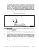
COMPRESSED AIR OPERATION AIR VALVE (32) CONNECT TO AIR SUPPLY FIGURE F To Operate, Using Compressed Air: 1. For best service, you should incorporate an oiler, regulator, and in-line filter, as shown in the diagram below. Hoses, couplers, oilers, regulators, and filters are all available at Harbor Freight Tools. NOTE: If an automatic oiler is not used, put 3-5 drops of pneumatic Tool Oil (not included) in the Long Ram Jack’s Quick Coupler (A41) before each use. (See Figure E.
Air Valve once again to release any remaining air pressure from the system. (See Figures B and F.) 6. When finished using the Long Ram Jack and shop crane, store the equipment in a clean, dry, safe location out of reach of children and other unauthorized people. INSPECTION, MAINTENANCE, AND CLEANING 1. Before each use, inspect the general condition of the Long Ram Jack.
TROUBLESHOOTING Problem Possible Causes Possible Solution Jack will not lift load. 1. Release Valve not tightly closed. 2. Overload condition. 3. Air supply inadequate. 4. Air trapped in system. 1. Close Release Valve firmly. 2. Do not exceed 8 ton lifting capacity. 3. Ensure adequate air supply. 4. Purge air from system. Jack will lift, but will not maintain pressure. 1. Release Valve not tightly closed. 2. Overload condition. 3. Hydraulic unit malfunction or defective seals. 1.
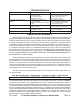
PARTS LIST & ASSEMBLY DIAGRAM Part Description Qty. Part Description Qty. Part Description Qty.
PARTS LIST & ASSEMBLY DIAGRAM A - AIR MOTOR Part Qty. Part Qty. Part A01 Air pump cylinder Description 1 A20 Air Cylinder Cap Description 1 A37 Valve Body Description Qty.