
Product manual


Item 61750 For technical questions, please call 1-888-866-5797. Page 8
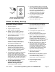
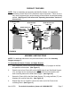
5. To connect the remaining Frame (85) to the two Side Stand Supports (76), follow
Steps #1, #2, #3, and #4. (See Figure C.)
SIDE
STAND
SUPPORT
(76)
FRAME
(85)
SCREW (77)
WASHER (83)
NUT (84)
SCREW (75)
WASHER (89)
NUT (90)
FIGURE C
UPPER
BRACKET
(74)
(mostly
hidden)
6. Place both Upper Brackets (74) on the top edges of the two Side Stand
Supports (76), and align the eight mounting holes (two on each end) of the
Brackets with the eight mounting holes (two on each end) of the Side Stand
Supports. (See Figure C.)
7. Secure both Upper Brackets (74) to the two Side Stand Supports (76), using
eight Bolts (77), Washers (93), and Nuts (74). (See Figure C.)
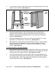
8. With assistance, carefully tip the assembled Stand on its side. Attach a Rubber
Foot (78) to each of the Stand’s four corners, using four Rubber Feet, four
Washers (80), and four Bolts (79). Then, place the Stand back in its upright
position. (See Figure D.)
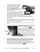
To Attach the Base to the Upper Bracket:
1. With assistance, place the Base (68) of the Belt/Disc Sander on top of the Upper
Brackets (74). Align the four threaded mounting holes on the Base with the four
mounting holes on the Upper Brackets. (See Figures B, and D.)
2. From underneath the Stand, secure the Base (68) to the Upper Brackets (74)
by inserting four Bolts (86), with four Washers (87), upward through the Stand’s
four mounting holes. Then, firmly tighten the four Bolts into the four threaded
mounting holes on the Base. (See Figure D.)