
Product manual


Item 61750 For technical questions, please call 1-888-866-5797. Page 7
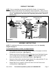
PRODUCT FEATURES
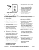
NOTE: Prior to assembling and operating the Belt/Disc Sander, it is important to
familiarize yourself with all of the machine’s major components. Failure to do so
may result in personal injury and/or damage to the machine and workpiece being
sanded. (See Figure B, and refer to the “Operating Instructions” section in
this manual.)
9" SANDING DISC
(32)
6" SANDING
BELT (1)
WORK TABLE (41)
MITER GAUGE
(39)
WORK STOP
(105)
POWER
SWITCH
(64)
POWER
CORD
(59)
KNOB/ADJUST NUT
ASSY. (38)
FIGURE B
SIDE STAND
SUPPORT (76)
FRAME (85)
BASE
(68)
DUST
GUARD
(22)
SANDING
BELT
FRAME (106)
ASSEMBLY INSTRUCTIONS
NOTE: For additional references to the parts listed below, refer to the Assembly
Diagram on page 17.
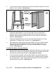
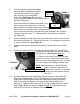
To Assemble the Stands, Frames, and Upper Bracket:
1. With assistance, position the two Side Stand Supports (76) upright on the floor
and parallel to one another. (See Figure C.)
2. Place the end of one Frame (85) on the inside edge of one Side Stand Support
(76), and align the two mounting holes on the end of the Frame with the two
lower mounting holes on the Side Stand Support. (See Figure C.)
3. Secure the Frame (85) to the Side Stand Support (76), using two Bolts (77), two
Washers (83), and two Nuts (84). (See Figure C.)
4. Repeat Steps #1, #2, and #3 to connect the other end of the Frame to the
remaining Stand. (See Figure C.)