
Product manual


Item 61750 For technical questions, please call 1-888-866-5797. Page 10
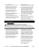
FIGURE G
Hole for Support Bar (56)
FIGURE F
Spindle
Pulley (24)
Motor Pulley
(26)
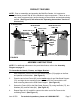
6. Carefully align both pulleys and tighten.
Use a flat head screwdriver through the
slot in the Dust Guard (22) to tighten
the Set Screw (23) on the Spindle
Pulley (24). (See Figure G.) Use a hex
key (not included) to tighten the Set Screw (25) on
the Motor Pulley (26).
7. Loosen the 4 Bolts (96) that hold the Motor (101)
just enough to let the Motor move. Move the
Motor towards the Spindle Pulley enough to let the
Belt (29) slip on over both Pulleys. Move the Motor
away from the Spindle Pulley until the Belt is tight enough so that, if pushed,
it doesn’t move more than
1
/
2
". Hold the Motor in place while you retighten
the 4 Bolts (96).
8. Put the Sanding Disc Plate (30) on the end of the shaft so that it’s flush with the
end of the Drive Shaft (13). Tighten its Set Screw (31), once again using the slot
in the Dust Guard (22). (See Figure G.)
9. Check to make sure the Sanding Disc Plate (30) is free of dirt, oil, and other
debris.
10. Remove the paper backing on the adhesive Sanding Disc (32), and stick the
Sanding Disc firmly and evenly onto the Sanding
Disc Plate (30). (See Figure I, page 11.)
11. Replace cover of the Dust Guard (22) and
tighten the 4 screws. Verify that the Dust Guard
does not contact the Sanding Disc (32). If it does,
you need to adjust the Sanding Disc Plate (30).
NOTE: When positioning the Work Table (41),
make sure there is more than
1
/
16
"
clearance but less than
1
/
8
" clearance
between the Table and the Sanding
Disc (32).
12. Insert the round end of the Support Bar (56) into the hole on the side of the
Base (68). (See Figure G.) Put the Table Support (51) over the end of the
Support Bar, with the tapered side of the Table Support facing the Sanding
Disc (32) and also the flat side of the Support Bar lined up with the Set
Screw (67). Tighten the Set Screw (50) on the Table Support Bracket. Set the
Table Support Bracket as shown in Figure J, page 12. Tighten the two Set
Screws (97) on the side of the Base to secure the bar.