PRODUCT SPECIFICATIONS Electrical Requirements 120 VAC / 60 Hz / 12 A Motor Rating 1 HP, 3450 RPM Ball Bearing Motor Overall Height 38.5" Table Surface Dimensions 6" x 12" Table Tilt 0 – 45 Degrees Work Table Options For Sanding Disc or Sanding Belt Use Belt Size 6" x 48" Disc Size 9" Diameter, PSA Type Belt Speed 1400 FPM Disk Speed 1800 RPM Weight 121 lb 4005911 WARNING SYMBOLS AND DEFINITIONS This is the safety alert symbol.
IMPORTANT SAFETY INFORMATION General Tool Safety Warnings Read all safety warnings and instructions. Failure to follow the warnings and instructions may result in electric shock, fire and/or serious injury. Save all warnings and instructions for future reference. 1. KEEP GUARDS IN PLACE and in working order. 2. REMOVE ADJUSTING KEYS AND WRENCHES. Form habit of checking to see that keys and adjusting wrenches are removed from tool before turning it on. 3. KEEP WORK AREA CLEAN.
13. DON’T OVERREACH. Keep proper footing and balance at all times. 14. MAINTAIN TOOLS WITH CARE. Keep tools sharp and clean for best and safest performance. Follow instructions for lubricating and changing accessories. 15. DISCONNECT TOOLS before servicing; when changing accessories, such as blades, bits, cutters, and the like. 16. REDUCE THE RISK OF UNINTENTIONAL STARTING. Make sure switch is in off position before plugging in. 17. USE RECOMMENDED ACCESSORIES.
Grounding Pin 125 VAC 3-Prong Plug and Outlet (for up to 125 VAC and up to 15 A) 7. This tool is intended for use on a circuit that has an outlet that looks like the one illustrated above in “125 VAC 3-Prong Plug and Outlet”. The tool has a grounding plug that looks like the plug illustrated above in “125 VAC 3-Prong Plug and Outlet”. 8. The outlet must be properly installed and grounded in accordance with all codes and ordinances. 9. Do not use an adapter to connect this tool to a different outlet.
17. People with pacemakers should consult their physician(s) before use. Electromagnetic fields in close proximity to heart pacemaker could cause pacemaker interference or pacemaker failure. 18. WARNING: Some dust created by power sanding, sawing, grinding, drilling, and other construction activities, contains chemicals known [to the State of California] to cause cancer, birth defects or other reproductive harm.
PRODUCT FEATURES NOTE: Prior to assembling and operating the Belt/Disc Sander, it is important to familiarize yourself with all of the machine’s major components. Failure to do so may result in personal injury and/or damage to the machine and workpiece being sanded. (See Figure B, and refer to the “Operating Instructions” section in this manual.
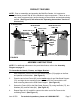
5. To connect the remaining Frame (85) to the two Side Stand Supports (76), follow Steps #1, #2, #3, and #4. (See Figure C.) SCREW (75) WASHER (89) NUT (90) UPPER BRACKET (74) (mostly hidden) SIDE STAND SUPPORT (76) SCREW (77) WASHER (83) NUT (84) FIGURE C FRAME (85) 6. Place both Upper Brackets (74) on the top edges of the two Side Stand Supports (76), and align the eight mounting holes (two on each end) of the Brackets with the eight mounting holes (two on each end) of the Side Stand Supports.
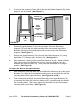
BOLT (86) WASHER (87) FIGURE D Bolt (79) WASHER (80) RUBBER FOOT (78) To Assemble the Pulleys, Sanding Disc Plate, and Table: 1. Remove the 4 screws from the cover on the Dust Guard (22) and set aside. 2. Line up the three bolt holes on the Dust Guard (22) with the threaded holes in the End Shield (19). Place a Washer (27) over each of 3 screw holes. Insert a Screw (28) into each hole and tighten. (See Figure E.) 3. This item is packed with tape on the shafts to keep the keys in place.
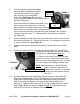
6. Carefully align both pulleys and tighten. Use a flat head screwdriver through the Spindle slot in the Dust Guard (22) to tighten Pulley (24) the Set Screw (23) on the Spindle Pulley (24). (See Figure G.) Use a hex key (not included) to tighten the Set Screw (25) on the Motor Pulley (26). FIGURE F 7. Loosen the 4 Bolts (96) that hold the Motor (101) Motor Pulley just enough to let the Motor move. Move the (26) Motor towards the Spindle Pulley enough to let the Belt (29) slip on over both Pulleys.
OPERATING INSTRUCTIONS To Install A Sanding Belt: 1. CAUTION: Always turn the Power Switch (64) to its “OFF” position and unplug the Power Cord (59) from its 110 volt electrical outlet before performing this procedure. (See Figure B.) 2. Loosen the two Knobs (107) in order to unlock the two Adjusting Nuts (108). (See Figure H, next page.) 3. Turn the two Adjusting Nuts (108) counterclockwise to allow the Sanding Belt (1) to be inserted onto the Sand Belt Frame (106). (See Figure H.) 4.
To Install a Sanding Disc: 1. CAUTION: Always turn the Power Switch (64) to its “OFF” position and unplug the Power Cord (59) SANDING DISC from its 110 volt (32) electrical outlet before performing SANDING DISC PLATE this procedure. (30) (See Figure B.) 2. Swing the Table Support (51) out of the way and remove the cover from the Dust Guard (22) as explained on page 9. Check to make sure the FIGURE I Sanding Disc Plate (30) is free of dirt, oil, and other debris. (See Figure I.) 3.
TABLE (41) TABLE (41) ANGLE GAUGE (42) KNOB (45) KNOB (45) ANGLE GAUGE (42) FIGURE J To Adjust The Angle Of The Miter Gauge: 1. The angle of the Miter Gauge (39) may be adjusted to the right 0 to 45 Degrees and to the left 0 to 45 Degrees. (See Figure K, next page.) 2. To adjust the angle of the Miter Gauge (39), slightly loosen the Miter Gauge Knob (38). (See Figure K.) 3. Observe the Angle Scale on the Miter Gauge (39).
To Adjust the Sand Belt Frame for Vertical Sanding: Loosen the two Nuts (5) on the Sanding Belt Frame (106), and with assistance raise the Sanding Belt Frame to its full vertical position. Then, firmly retighten the two Nuts to lock the Sanding Belt Frame in place. (See Figure L.) NUT (5) SANDING BELT FRAME (106) (VERTICAL POSITION) FIGURE L To Adjust the Position of the Table: 1.
END VIEW WORK TABLE (41) SANDING BELT FRAME (106) SANDING BELT (1) SUPPORT BAR (56) SET SCREW (67) FIGURE M SIDE VIEW WORK TABLE (41) SUPPORT BAR (56) SET SCREW (97) To Perform Horizontal Sanding with the Sanding Belt: 1. CAUTION: Before each use, inspect the condition of the Sanding Belt (1). Look for tearing, excessive wear, or other damage to the Sanding Belt. Never use a Sanding Belt that is damaged. When replacing, never use an inexpensive, low quality Sanding Belt. 2.
To Perform Horizontal Sanding with the Sanding Disc: 1. CAUTION: Before each use, inspect the condition of the Sanding Disc (32). Look for tearing, excessive wear, or other damage to the Sanding Disc. Never use a Sanding Disc that is damaged. When replacing, never use an inexpensive, low quality Sanding Disc. 2. NOTE: The Sanding Disc (32) is typically used for smaller workpieces. 3. Plug the Power Cord (59) into a grounded, 110 Volt electrical outlet. (See Figure B.) 4.
INSPECTION, MAINTENANCE, AND CLEANING 1. CAUTION: Always turn the Power Switch (64) to its “OFF” position and unplug the Power Cord (59) from its 110 volt electrical outlet before performing any inspection, adjustments, maintenance, or cleaning. 2. BEFORE EACH USE, inspect the general condition of the Belt/Disc Sander.
PARTS LIST Part 1 2 3 4 5 6 7 8 9 10 11 12 13 14 15 16 17 18 19 20 21 22 23 24 25 26 27 28 29 30 31 32 33 34 35 36 37 Description Sanding Belt Bearing Plate 3AMI-12 Retaining Ring Ball bearing 6201ZZ 8mm Hex Nut 8mm Lock Washer Drum Cover 6-8 x 10mm Set Screw 6 x 10mm Pan Head Screw Dust Deflector Drive Drum Key C5 x 55 Drive Shaft Ball Bearing 6003ZZ 1XØ33.
ASSEMBLY DIAGRAM 47 48 45 44 43 41 40 42 46 39 49 38 50 52 51 54 34 35 36 37 53 55 33 56 32 57 59 31 58 60 30 61 62 28 63 66 80 81 82 77 76 73 74 68 84 65 89 85 71 91 86 87 88 92 93 19 101 70 21 20 98 99 100 75 90 22 67 72 69 83 26 25 27 64 79 78 24 23 29 102 18 17 16 97 94 14 104 13 103 96 15 105 95 9 10 11 8 12 7 6 106 107 5 4 108 3 109 110 112 2 111 1 113 114 115 Record Product’s Serial Number Here: Note: If product has no ser
Limited 90 Day Warranty Harbor Freight Tools Co. makes every effort to assure that its products meet high quality and durability standards, and warrants to the original purchaser that this product is free from defects in materials and workmanship for the period of 90 days from the date of purchase.