
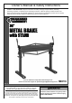
Product manual

Page 2 For technical questions, please call 1-888-866-5797. Item 91012
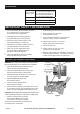
Specifications
Bending Capacity
(Gauge x Width)
Up to 12 Gauge Sheet Metal at 18″
Up to 16 Gauge Sheet Metal at 36″
Up to 16 Gauge Mild Steel at 18″
Up to 20 Gauge Mild Steel at 36″
Up to 22 Gauge Stainless Steel
Bend Angles 0 to 120°
Max. Box Depth 3″
Max. Beam Lift 7/8″
IMPORTANT SAFETY INFORMATION
1. Do not exceed the maximum bending capacities
of 18” wide stock (for 12 gauge steel) or
36” wide stock (for 16 gauge steel.)
2. Wear ANSI-approved safety goggles and
heavy-duty work gloves during assembly.
3. Keep fingers clear of Press Plate (14) and
Press Plate Assembly (17) during use.
4. Assemble only according to these instructions.
Improper assembly can create hazards.
5. Place only on a flat, stable surface able
to support weight of Metal Brake, item
being bent, and the bending force.
6. Verify that installation surface has no hidden
utility lines before drilling the holes.
7. Keep assembly and work area clean and well lit.
8. Keep bystanders out of the area
during assembly and use.
9. Do not assemble when tired or when under the
influence of drugs, alcohol or medication.
10. This product is not a toy. Do not allow
children to play with or near this item.
11. Use as intended only.
12. Inspect before every use; do not use
if parts are loose or damaged.
13. Maintain product labels and nameplates. These carry
important safety information. If unreadable or missing,
contact Harbor Freight Tools for a replacement.
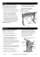
Assembly and Installation Instructions
WARNING! The weight of the Brake and Stand requires
that two people assist in the assembly and installation.
1. Place the Metal Brake (back side) on the floor
with the mounting feet facing forward.
2. Place the Left Brake Stand (20) mounting pad
against the left mounting foot of the Brake.
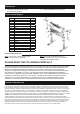
3. Assemble with Bolt (12), Washer (11), and Nut (10)
as shown in Figure A. Securely tighten.
4. Mount the Right Brake Stand (19)
as described in Step 2.
5. Using two people, carefully lift the
Brake and Stand it upright.
6. Place the Brake and Stand in the location where it will
be mounted to the floor, then mark through the 1/2 inch
holes in the Left and Right Brake Stands (20 and 19).
CAUTION! Before drilling the mounting holes, verify that you
will not be drilling through any utility lines or water pipes.
7. Drill four mounting holes into the floor
and secure the Brake with four bolts*,
lock washers, and nuts (not supplied).
*Use expansion anchor bolts for concrete floors.
For wooden floors, use lag bolts.
Nut (10)
and Washer
(11)
Bolt (12)
Left and Right
Brake Stands
(19, 20)
Body (18)
Figure A