Table of Contents SAFETY Safety.......................................................... 2 Specifications.............................................. 4 Installation................................................... 6 Operation..................................................... 7 Maintenance................................................ 8 Parts List and Assembly Diagram.............. 10 Warranty.....................................................
Service Specific Safety Warnings 3. Use on flat, level, hard surface capable of supporting load. 4. Wear ANSI-approved safety goggles during use. 5. Prevent trailer wheels from moving using wheel chocks while raising or lowering. 6. Before towing, fully raise Trailer Jack. Jack must always be retracted when towing the trailer. 7. Keep out from under Jack and tongue when applying and releasing load, when Jack is supporting load, or when moving trailer. 8. Inspect before use.
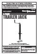
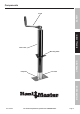
Functional Description Specifications SAFETY Weight Capacity 2000 lb. Travel Length 14" Lift Range 10-1/2"– 24-1/2" Application For use with A-frame trailers Hardware (sold separately) 3 bolts 3/8" D x 1" L (grade 5 or better), 3 lock nuts, 6 washers INSTALLATION OPERATION MAINTENANCE Page 4 For technical questions, please call 1-888-866-5797.
Components INSTALLATION SAFETY Crank Outer Tube Lock Pin MAINTENANCE Footplate OPERATION Mounting Plate Item 61622 For technical questions, please call 1-888-866-5797.
Installation Instructions Read the ENTIRE IMPORTANT SAFETY INFORMATION section at the beginning of this manual including all text under subheadings therein before set up or use of this product. SAFETY Note: For additional information regarding the parts listed in the following pages, refer to Parts List and Diagram on page 10. Mounting INSTALLATION This Trailer Jack is designed specifically for use with an A-frame hitch.
Operation Instructions Read the ENTIRE IMPORTANT SAFETY INFORMATION section at the beginning of this manual including all text under subheadings therein before set up or use of this product. 2. Pull the Crank (2) out so that the knob is on top. Rotate the Crank clockwise to extend the Jack and raise the trailer hitch above the level of the towing vehicle’s hitch ball. Once the trailer is at the desired height, fold the Crank over so that the knob is facing downward.
User-Maintenance Instructions Procedures not specifically explained in this manual must be performed only by a qualified technician. SAFETY TO PREVENT SERIOUS INJURY: Remove Jack from trailer before performing any inspection, maintenance, or cleaning procedures. TO PREVENT SERIOUS INJURY FROM TOOL FAILURE: Do not use damaged equipment. If abnormal noise or vibration occurs, have the problem corrected before further use. Cleaning, Maintenance, and Lubrication INSTALLATION 1.
OPERATION INSTALLATION THE MANUFACTURER AND/OR DISTRIBUTOR HAS PROVIDED THE PARTS LIST AND ASSEMBLY DIAGRAM IN THIS MANUAL AS A REFERENCE TOOL ONLY. NEITHER THE MANUFACTURER OR DISTRIBUTOR MAKES ANY REPRESENTATION OR WARRANTY OF ANY KIND TO THE BUYER THAT HE OR SHE IS QUALIFIED TO MAKE ANY REPAIRS TO THE PRODUCT, OR THAT HE OR SHE IS QUALIFIED TO REPLACE ANY PARTS OF THE PRODUCT.
Parts List and Diagram Parts List SAFETY Part 1 2 3 4 5 6 Description Lock Nut M6 Crank Bolt M6 x 38 Washer Outer Tube Bearing Qty 1 1 1 1 1 1 Part 7 8 9 10 11 12 Washer Jack Screw Nut Inner Tube Lock Pin Foot Plate Description Qty 1 1 1 1 1 1 INSTALLATION OPERATION MAINTENANCE Record Product’s Serial Number Here: Note: If product has no serial number, record month and year of purchase instead.
INSTALLATION SAFETY Assembly Diagram 6 7 8 9 OPERATION 11 10 12 MAINTENANCE ttt Item 61622 For technical questions, please call 1-888-866-5797.
Limited 90 Day Warranty Harbor Freight Tools Co. makes every effort to assure that its products meet high quality and durability standards, and warrants to the original purchaser that this product is free from defects in materials and workmanship for the period of 90 days from the date of purchase.