
Product manual

Page 5For technical questions, please call 1-888-866-5797.Item 69514
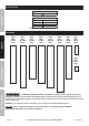
1.
2 5
2 4
2 3
2 2
3 0
2 1
2 6
2 7
2 8
2 9
2 3
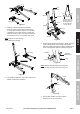
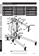
Figure A
(Assembled)
Slide the Legs into the front of the Base
and Lock Legs in place using the Lock Pins.
To insert the Lock Pins, lift up on front of Base
until holes line up. After all four Lock Pins are
inserted, insert one R-Pin through small hole at
end of each Lock Pin until it snaps into place.
Note: Make sure Lock Pins are
secure before proceeding.
2.
Base Assembly
9 10
8
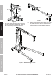
(Assembled)
Figure B
Use the Bolts, Washers, and Nuts to secure the
bottom of the Post to the Base.
3.
Figure C
Washer
Washers
Nut
Nut
Post
Support
Bolt (15)
Bolt (15)
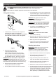
Bolt (16)
The bends of the
Supports face out
at the top and in
at the bottom as
shown above.
Support
Post
Leg Leg
Support
Use two Bolts, Washers and Nuts to fasten the lower
ends of the Supports to the inside of the Frame,
then use one Bolt, Washer and Nut to fasten the top
ends of the Supports and the Handle to the Post.
Handle
Post
Support
Support
(Not shown)
Figure D
Note: Slide the Handle between the Supports
and Post, align all holes, then secure in place.
4.
Figure E
Washer
Boom
Nut
Bolt (16)
Use the Bolt, Washer and Nut to attach
the Boom to the top of the Post.
SAFETYOPERATIONMAINTENANCE SETUP