Table of Contents SAFETY Safety ......................................................... 2 Specifications ............................................. 4 Setup .......................................................... 4 Operation .................................................... 7 Maintenance ............................................... 8 Parts Lists and Diagrams .......................... 10 Warranty ....................................................
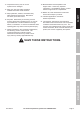
14. Keep your work area clean and well lit. Cluttered work areas invite accidents. 15. Keep bystanders, children, and visitors away while operating Engine Crane. Distractions can cause you to lose control. 16. Stay alert. Watch what you are doing, and use common sense when operating a jack. Do not use a jack while tired or under the influence of drugs, alcohol, or medication. A moment of inattention while operating jacks may result in serious personal injury. 17.
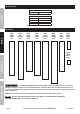
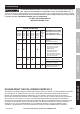
Specifications Specifications Jack Capacity 8 Ton SAFETY Boom Positions 2 Ton 1-1/2 Ton 1 Ton 1/2 Ton 84 IN. 89 IN. 95 IN. 100 IN. Meets 2005 ANSI/ASME PALD standards. Assembly SETUP Part #32 14x90 mm Part #8 14x100 mm Part #11 16x80 mm Part #20 16x90 mm Part #15 16x100 mm Part #16 16x110 mm Part #2 12x80 mm Part #25 8x20 mm Part #29 8x12 mm OPERATION MAINTENANCE TO PREVENT SERIOUS INJURY AND DEATH: The correct bolts must be used during assembly.
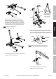
2 1 2 6 Nut 2 3 3 0 2 4 Washer 2 7 2 8 Post 2 92 3 Leg Bolt (16) Support (Assembled) Post Figure A Support 1. Slide the Legs into the front of the Base and Lock Legs in place using the Lock Pins. To insert the Lock Pins, lift up on front of Base until holes line up. After all four Lock Pins are inserted, insert one R-Pin through small hole at end of each Lock Pin until it snaps into place.
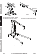
Nut Washer Nut Washer Bolt (11) SAFETY Jack Bolt (32) Boom Extension Nut Washer Nut Washer Bolt (20) Figure G Figure F 5. Use a Bolt, Washer and Nut to attach lower end of the Jack to the Post and another Bolt, Washer and Nut to attach the top of the Jack to the Boom. Bolt (2) SETUP 6. Slide the Boom Extension into the Boom and use the Bolt, Washer and Nut to secure at the desired load rating. Use the Bolt, Washer and Nut to attach the Hook and Chain to the end of the Boom Extension.
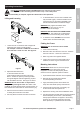
Operating Instructions Note: Once Assembly is complete, tighten ALL Bolts before initial operation. 5. To raise the Boom, turn the Jack’s release valve fully clockwise (right). Insert the Handle into the Jack and pump (up and down) repeatedly until the item has been lifted to the desired height. Lifting and Lowering SAFETY Read ENTIRE IMPORTANT SAFETY INFORMATION section at beginning of this manual including all text under subheadings therein before set up or use of this product.
Maintenance and Servicing Procedures not specifically explained in this manual must be performed only by a qualified technician. SAFETY TO PREVENT SERIOUS INJURY FROM ACCIDENTAL OPERATION: Do not use damaged equipment. If abnormal noise or vibration occurs, have the problem corrected before further use. Cleaning, Maintenance, and Lubrication SETUP 1. Before each use, inspect the general condition of the Jack.
TO PREVENT SERIOUS INJURY: Use caution when troubleshooting malfunctioning jack. Stay clear of supported load. Completely resolve all problems before use. If solutions presented in Troubleshooting guide do not solve the problem, have a qualified technician inspect and repair jack before use. After jack is repaired: Test it carefully without a load by raising and lowering it fully, checking for proper operation, BEFORE RETURNING JACK TO OPERATION.
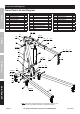
Parts Lists and Diagrams Crane Parts List and Diagram SAFETY Part 1 2 3 4 5 6 7 8 9 10 11 Description Hook & Chain Hex Bolt M12x80 Lock Washer Ø12 Flat Washer Ø12 Hex Nut M12 Boom Extension Boom Hex Bolt M14x100 Flat Washer Ø14 Hex Nut M14 Hex Bolt M16x80 Qty 1 1 1 1 1 1 1 2 3 3 1 Part 12 13 14 15 16 17 18 19 20 21 12 14 16 Description Flat Washer Ø16 Hex Nut M16 Main Post Hex Bolt M16x100 Hex Bolt M16x110 Support Handle 8 Ton Long Ram Jack Hex Bolt M16x90 Base Qty 6 6 1 2 2 2 1 1 1 1 Part 22 23 2
Jack Parts List and Diagram 1A 2A 3A 4A 5A 6A 7A 8A 9A 10A 11A 12A Description Piston Rod O-Ring Top Cap Rectangle Ring Cover Cylinder Piston Socket Locking Spring Axis Pin Dust Ring Pump Body Qty 1 1 1 1 1 1 1 1 3 2 1 1 Part 13A 14A 15A 16A 17A 18A 19A 20A 21A 22A 23A 24A Description Qty Pump Core Snap Ring O-Ring Washer Base Bolt M5x12 Trapezoid Ring Bowl Ring O-Ring Piston Washer Steel Ball Ø4 1 1 1 1 1 2 1 1 1 1 1 1 Part 25A 26A 27A 28A 29A 30A 31A 32A 33A 34A Description Spring Base Rectangl
Limited 90 Day Warranty Harbor Freight Tools Co. makes every effort to assure that its products meet high quality and durability standards, and warrants to the original purchaser that this product is free from defects in materials and workmanship for the period of 90 days from the date of purchase.
Garantía limitada de 90 días Harbor Freight Tools Co. hace todo lo posible para asegurar que sus productos cumplen con altos estándares de calidad y durabilidad, y garantiza al comprador original que este producto está libre de defectos en sus materiales y mano de obra durante un plazo de 90 días a partir de la fecha de compra.
Lista de piezas y diagrama del gato Pieza 1A 2A 3A 4A 5A 6A 7A 8A 9A 10A 11A 12A Descripción Vástago del pistón Junta tórica Tope superior Aro rectángulo Cubierta Cilindro Pistón Receptáculo Resorte de bloqueo Pasador del eje Anillo guardapolvo Carcasa de la bomba 1 1 1 1 1 1 1 1 3 2 1 1 Pieza 13A 14A 15A 16A 17A 18A 19A 20A 21A 22A 23A 24A Descripción Núcleo de la bomba Anillo de fijación Junta tórica Arandela Base Perno M5x12 Anillo trapezoidal Anillo embudo Junta tórica Pistón Arandela Bola de acer
Listas de piezas y diagramas Lista de piezas y diagrama de la grúa SEGURIDAD Pieza 1 2 3 4 5 6 7 8 9 10 11 Descripción Gancho y cadena Perno de cabeza hexagonal M12x80 Arandela de seguridad Ø12 Arandela plana Ø12 Tuerca de cabeza hexagonal M12 Extensión del brazo Brazo Perno de cabeza hexagonal M14x100 Arandela plana Ø14 Tuerca de cabeza hexagonal M14 Perno de cabeza hexagonal M16x80 1 1 1 1 1 1 1 2 3 3 1 12 CONFIGURACIóN 16 Pieza 12 13 14 15 16 17 18 19 20 21 Descripción Arandela plana Ø16 Tuerca
Resolución de problemas ADVERTENCIA PARA EVITAR LESIONES GRAVES: Tenga cuidado al solucionar un mal funcionamiento del gato. Manténgase alejado de la carga elevada. Solucione completamente todos los problemas antes de su uso.
Mantenimiento y servicio técnico SEGURIDAD Los procedimientos que no se explican específicamente en este manual deben ser realizados únicamente por un técnico calificado. ADVERTENCIA PARA EVITAR LESIONES GRAVES CONSECUENCIA DE UN FUNCIONAMIENTO ACCIDENTAL: No utilice el equipo si está dañado. Si detecta ruidos o vibraciones anormales, corrija el problema antes de su uso. Limpieza, mantenimiento y lubricación CONFIGURACIóN 1. Antes de cada uso, inspeccione el estado general del gato.
Instrucciones para la operación Antes de instalar o usar este producto, lea la TOTALIDAD DE LA SECCIóN "INFORMACIóN IMPORTANTE SOBRE SEGURIDAD" que se encuentra al comienzo de este manual, incluyendo todos los textos debajo de los subtítulos. Nota: Una vez finalizado el ensamblaje, ajuste TODOS los pernos antes de ponerla en funcionamiento por primera vez. Elevación y descenso . . . Carga de 3/4 t. . 5.
Tuerca Arandela SEGURIDAD Tuerca Arandela Perno (11) Gato Perno (32) Extensión del brazo Tuerca Arandela Tuerca Arandela Perno (20) Figura I Figura H CONFIGURACIóN 5. Utilice un perno, una arandela y una tuerca para sujetar el extremo inferior del gato al poste, y otro perno, otra arandela y otra tuerca para sujetar la parte superior del gato al brazo. Perno (2) 6.
2 2 2 1 2 6 2 3 3 0 2 4 2 5 2 8 2 7 Tuerca Arandela Poste 2 92 3 Pata Perno (16) (Ensamblado) Figura C Soporte 1. Deslice las patas dentro de la parte delantera de la base y bloquéelas en su lugar utilizando los pasadores de bloqueo. Para insertar los pasadores de bloqueo, levante el frente de la base hasta lograr la alineación de los orificios.
Especificaciones Especificaciones SEGURIDAD Capacidad del gato 8 t. Posiciones del brazo 2 t. 1-1/2 t. 1 t. 1/2 t. 84 pulg. 89 pulg. 95 pulg. 100 pulg.
11. Verifique que el gato de repuesto tenga la misma capacidad nominal, los mismos lugares de montaje y la misma longitud máxima. 12. No apta para usos aeronáuticos. 13. Inspeccione la grúa antes de cada uso; no la utilice si hay piezas sueltas o dañadas. 14. Mantenga el área de trabajo limpia y bien iluminada. Los lugares de trabajo desordenados facilitan los accidentes. 15. Mantenga alejados a los curiosos, los niños y los visitantes mientras opere la grúa para motores.
SEGURIDAD Seguridad ................................................... 2 Especificaciones ......................................... 4 Instalación .................................................. 4 Funcionamiento .......................................... 7 Contenido Mantenimiento ............................................ 8 Listas de piezas y diagramas ................... 10 Garantía.....................................................