Table of Contents SAFETY Safety ......................................................... 2 Assembly .................................................... 6 Specifications ............................................ 17 Operation ................................................... 17 Maintenance .............................................. 25 Parts List and Diagram .............................. 26 Reporting Safety Defects........................... 28 Warranty ..........................................
IMPORTANT SAFETY INFORMATION SAFETY Read all safety warnings and instructions. Failure to follow the warnings and instructions may result in serious injury. Save all warnings and instructions for future reference. The warnings, precautions, and instructions discussed in this instruction manual cannot cover all possible conditions and situations that may occur.
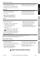
Operation Safety Note: Selected recommendations in this section are adapted from TOWING A TRAILER Being Equipped for Safety, published by NHTSA. For full details, see that document. SAFETY 1. This Trailer is not a toy. Do not allow children to play on or near this item. 2. Take time to practice before driving on main roads. 3. Never allow anyone to ride in or on the trailer. 4. Do not transport animals in this trailer. Before Each Use 1. Check Tire (13) condition and air pressure. 2.
Downgrades and Upgrades SAFETY 2. On long downgrades, apply brakes at intervals to keep speed in check. Never leave brakes on for extended periods of time or they may overheat. 3. Some tow vehicles have specifically calibrated transmission tow-modes. Be sure to use the tow-mode recommended by the manufacturer. Backing Up 1. Put your hand at the bottom of the steering wheel. To turn left, move your hand left. To turn right, move your hand right. 4.
Assembly Instructions Read the ENTIRE IMPORTANT SAFETY INFORMATION section at the beginning of this manual including all text under subheadings therein before set up or use of this Trailer. SAFETY Note: For additional information regarding the parts listed in the following pages, refer to Parts List and Diagram on page 26. 1. Lay out the Front Left Side Rail (15), Front Right Side Rail (27), Front Member (28) and two Cross Members (21).
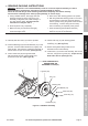
3. Attach the Front and Rear Bed Rail Assemblies using two M10 x 20 Bolts (31) and M10 Nuts (33). (See Figure C.) SAFETY REAR OF TRAILER (33) (33) (31) (31) ASSEMBLY Rear Bed Rail Assembly Front Bed Rail Assembly FRONT OF TRAILER Figure C: Attaching Front and Rear Bed Rail Assemblies 6. Attach the Coupler Base (3) to the Left and Right Drawbar Rails using six M10 x 20 Bolts (31) and M10 Nuts (33).
7. With assistance, turn the frame upside down. 8. Attach the Right Spring Hanger (26) to the Front Right Side Rail (27) using two M10 x 20 Bolts (31) and M10 Nuts (33). (See Figure E.) SAFETY 9. Attach the Left Spring Hanger (17) to the Front Left Side Rail (15) using two M10 x 20 Bolts (31) and M10 Nuts (33). 10. Attach the Right Spring Hanger (26) to the Rear Right Side Rail (22) using one M10 x 30 bolt (7), two M10 x 25 Carriage Bolts (25) and three M10 Nuts (33). (See Figure E.) 11.
18. BEARING PACKING INSTRUCTIONS d. Place fresh, clean bearing grease in the packer. b. Allow all pieces to dry completely. e. With the grease-filled bearing packer in one hand and the bearing in the other, press the bearing into the grease, forcing the grease inside the slots in the bearing. Continue doing this until every slot in the bearing is completely full of grease. c. Make sure that your hands are thoroughly clean and the bearing packer (not included) is also thoroughly clean. f.
25. With assistance, turn the Trailer assembly right side up. SAFETY 26. Attach the Coupler (2) to the Coupler Base (3), using two M12 x 75 Bolts (16) and M12 Nuts (35). Thread one of the M12 x 75 Bolts (16) through the center link of the Safety Chain (1). (See Figure H.) 27. Lock the Coupler Trigger, using Locking Pin (47) and 2mm R-Clip (43). (See Figure H.) 28. Attach the Light Brackets (24) to the Rear Left Side Rail (20) and Rear Right Side Rail (22) using M10 x 20 Bolts (31) and M10 Nuts (33).
40. Leave about 18" of wire beyond the Coupler (2), and run the wiring harness along the inside of the Right Drawbar Rail (5) to the Front Right Side Rail (27). Then, split the yellow/brown wires from the green/brown wires. 34. Have a qualified service technician install a 4-wire, 12VDC connector in the trunk area of your vehicle. 41. Run the yellow/brown wires along the inside of the Front Cross Member (21) to the Side Running Light (45) located on the Front Left Side Rail (15).
WIRE HARNESS CONNECTOR PLUG WHITE GROUND WIRE SAFETY BROWN YELLOW GREEN BROWN WIRE LEAD FROM SIDE RUNNING LIGHT (45) WIRE LEAD FROM SIDE RUNNING LIGHT (45) ASSEMBLY LEAVE 16" EXCESS WIRE HERE. YELLOW LEAVE 16" EXCESS WIRE HERE. GREEN BROWN BROWN BROWN YELLOW GREEN BROWN RIGHT TAIL LIGHT (23R) LEFT TAIL LIGHT (23L) Figure I: Trailer Wiring OPERATION MAINTENANCE Page 12 For technical questions, please call 1-800-444-3353.
SAFETY 4-pin connector White ground wire to trailer tongue Brown Brown Green ASSEMBLY Yellow side marker lights Black wire clip OPERATION Yellow Brown Brown tail light wire Right light (Green lead) Wired same as left side Left light (Yellow lead) Brown: Green: Yellow: White: KEY / COLOR CODES Tail and side marker lights Right directional and stop light Left directional and stop light Ground to trailer frame Indicates wire nut connection Figure J: Wiring Diagram Item 69897 For technical qu
Optional Bed Installation (not included) SAFETY Minimum Required Parts: a. Qty. 2: 2 3/4" x 48" x 48" Plywood (not included). b. Qty. 24-30: 24-30 3/8" Cross Head Bolts (not included). c. Qty. 24-30: 24-30 3/8" Flat Washers (not included). d. Qty. 24-30: 24-30 3/8" Spring Washers (not included). e. Qty. 24-30: 24-30 3/8" Nuts (not included). 1. Drill 3/8" mounting holes as shown in Figure K. 2.
Optional Rail Installation (not included) SAFETY Minimum Required Parts: a. Qty. 8: 8 1.6" x 3.5" x 27" wood strips (not included). b. Qty. 6: 6 0.75" x 3.5" x 48" wood strips (not included). c. Qty. 6: 6 0.75" x 3.5" x 94.5" wood strips (not included). d. Qty. 4: 4 0.175" x 2" x 2" x 3.5" Steel Angle (not included). e. Qty. 16: 16 3/8" x 1-3/4" Bolt (not included). f. Qty. 8: 8 3/8" x 2-3/8" Bolt (not included). g. Qty. 48: 48 3/8" x 2-3/8" Bolt (not included). h. Qty.
2. Attach the Side Rails and Front End/Back End Rails to the Stakes, using 3/8" x 3-3/8" Cross Head Bolts, 3/8" Flat Washers, and 3/8" Nuts. 3. Attach the Connecting Plates to the Side Rails and Front End/Back End Rails, using 3/8" x 1-3/4" Cross Head Bolts and 3/8" Nuts.
Specifications 1,720 lb. 4 Ft. x 8 Ft. 2" 12" x 4" 5 Per Wheel 5.30-12 80 PSI, Cold II SAFETY Maximum Capacity Payload Bed Dimensions Hitch Ball Size Wheel Rim Diameter/Width Quantity Wheel Lug Nuts Tire Size Required Tire Air Pressure Hitch Class Read the ENTIRE IMPORTANT SAFETY INFORMATION section at the beginning of this manual including all text under subheadings therein before set up or use of this Trailer. Before each use 2. Make sure wheel lug nuts/bolts are properly tightened. 3.
Connection WARNING! Only use a 2" ball hitch (not included) on the towing vehicle. SAFETY 1. To reduce friction between the hitch ball and Hitch Coupler (2), apply a thin layer of heavy weight grease over the hitch ball. 2. Remove the R-Clip (43) and Locking Pin (47). 2 mm R-Clip (43) Locking Pin (47) ASSEMBLY Hitch Coupler (2) Figure N: Remove R-Clip and Lock Pin 3. Then, pull up on the Trigger and lift up on the Handle. 4.
Tire information • Accessory weight meansmeans the combined weight of automatic transmission, power steering, power brakes, power windows, power seats, radio, and heater, to the extent that these items are available as factory-installed equipment. • Maximum tire width means- the greater of either the linear distance between the exterior edges of the carcass or the linear distance between the exterior edges of the tread, both being measured parallel to the rolling axis of the tire.
Tire Markings Inner diameter in inches Load index and Speed rating* European tire certificate* Section width in inches SAFETY U.S. DOT tire identification number Tire ply composition and materials used Maximum permissible inflation pressure ASSEMBLY Maximum load rating Trailer tire *Information not required by U.S. DOT • Section width- This number gives the width of the tire in inches. The larger the number, the wider the tire. (The markings on the example tire diagram show 4.80.
Code MPH F G J K L M 50 56 62 68 75 81 Code MPH N P Q R S T 87 94 100 106 112 118 • Tire Ply Composition and Materials UsedUsed The number of plies indicates the number of layers of rubber-coated fabric in the tire. In general, the greater the number of plies, the more weight a tire can support. Tire manufacturers also must indicate the materials in the tire, which include steel, nylon, polyester, and others.
Tire care Checking Tire Pressure SAFETY Note: Underinflated tires can decrease handling, stopping performance, traction, tire life, and load-carrying capability, in addition to causing other negative and hazardous effects, including tire failure. Overinflated tires are at greater risk of an impact break, where the tread and casing break when striking a hard edge, often opening a huge gash across the tread. Incorrect inflation pressure also increases tires wear rate.
Tire Balance and Alignment Tire Repair To properly repair a punctured tire, the hole needs to be properly plugged and patched from the inside of the tire. Tread punctures can be repaired if they are not too large. Sidewall punctures should not be repaired, the tire needs to be replaced if the sidewall is damaged. Tires should be removed from the rim to be inspected before being plugged and patched. A qualified mechanic should remove the tire from the rim, perform the repair, and remount the tire.
Acceleration and Passing 1. When passing a slower vehicle or changing lanes, signal well in advance and make sure you allow extra distance to clear the vehicle before you pull back into the lane. SAFETY 2. Pass on level terrain with plenty of clearance. Avoid passing on steep upgrades or downgrades. 3. If necessary, downshift for improved acceleration or speed maintenance. 4. When passing on narrow roads, be careful not to go onto a soft shoulder.
Maintenance SAFETY Procedures not specifically explained in this manual must be performed only by a qualified technician. TO PREVENT SERIOUS INJURY FROM TOOL FAILURE: Do not use damaged equipment. If abnormal noise or vibration occurs, have the problem corrected before further use. Note: Tow vehicles often have more frequent maintenance requirements, including changes of engine and transmission oils and filters, lubrication of components, and cooling system checks.
Parts List and Diagram PLEASE READ THE FOLLOWING CAREFULLY SAFETY THE MANUFACTURER AND/OR DISTRIBUTOR HAS PROVIDED THE PARTS LIST AND ASSEMBLY DIAGRAM IN THIS MANUAL AS A REFERENCE TOOL ONLY. NEITHER THE MANUFACTURER OR DISTRIBUTOR MAKES ANY REPRESENTATION OR WARRANTY OF ANY KIND TO THE BUYER THAT HE OR SHE IS QUALIFIED TO MAKE ANY REPAIRS TO THE PRODUCT, OR THAT HE OR SHE IS QUALIFIED TO REPLACE ANY PARTS OF THE PRODUCT.
Item 69897 43 16 For technical questions, please call 1-800-444-3353.
Reporting Safety Defects If you believe that your vehicle has a defect which could cause a crash or could cause injury or death, you should immediately inform the National Traffic Safety Administration (NHTSA) in addition to notifying Changzhou Nanxiashu Tool Company. If NHTSA receives similar complaints, it may open an investigation. And if it finds that a safety defect exist in a group of vehicles, it may order a recall and remedy campaign.