Owner’s Manual & Safety Instructions Save This Manual Keep this manual for the safety warnings and precautions, assembly, operating, inspection, maintenance and cleaning procedures. Write the product’s serial number in the back of the manual near the assembly diagram (or month and year of purchase if product has no number). Keep this manual and the receipt in a safe and dry place for future reference. ITEMS 41188 69513 REV 14l Visit our website at: http://www.harborfreight.
Table of Contents SAFETY Safety..................................................2 Specifications......................................4 Assembly.............................................4 Operation............................................10 Maintenance.......................................14 Parts List and Assembly Diagram......18 Warranty.............................................20 WARNING SYMBOLS AND DEFINITIONS This is the safety alert symbol.
1. Assemble completely according to instructions 5. Do not assemble when tired or when under and install Height Pins and R-pins before use. the influence of drugs or medication. Improper assembly can create hazards. 6. Weight capacity and other product 2. Assemble or adjust height capabilities apply to properly and only with assistance. completely assembled product only. 3. Keep assembly area clean and well lit. 4. Keep bystanders out of the area during assembly. 7.
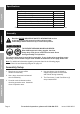
Specifications SAFETY Load Rating Minimum Overall Height Maximum Overall Height Overall Width Minimum Vertical Clearance* (under I-Beam) Maximum Vertical Clearance* (under I-Beam) Clearance Between Posts I-Beam 2,000 lb 99" 147-1/2" 128" 94" 142-1/2" 93-11/16" 3″W x 5″H * Factor in size of beam trolley and hoist when determining required clearance.
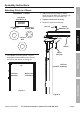
Assembly Instructions Hardware - 8 each: (29) Beam Bolt M12 x 35 Threaded Shaft Size 3. Tighten connections securely. 4. Repeat for right Post Assembly. (15) Spring Washer M12 (16) Nut M12 Nut (16) Spring Washer (15) Washer (19) ASSEMBLY (19) Washer M12 2. Attach Left Post Assembly to I‑Beam using four Beam Bolts (29), Washers (19), Spring Washers (15), and Nuts (16). SAFETY Attaching Posts to I- Beam I-Beam I-Beam (4) Left Post Assembly OPERATION 1. Lay I-Beam (4) on the ground.
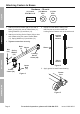
Attaching Casters to Bases Hardware - 16 each: SAFETY (11) Caster Bolt M10 x 25 (12) Washer M10 (13) Nut M10 Threaded Shaft Size 1. Attach one Swivel Caster (9a) to one end of Base (3) using four sets of Caster Bolts (11), Spring Washers (12) and Nuts (13). 4. Repeat for other Base, making sure that Sleeves are to the outside and Locking Swivel Casters are on the same end. ASSEMBLY 2.
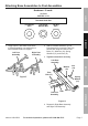
Attaching Base Assemblies to Post Assemblies Hardware - 8 each: SAFETY (17) Post Bolt M12 x 110 Threaded Shaft Size 1. Using helpers, raise Base Plate ends of Post Assemblies onto sawhorses or other suitable means of support. Left Post Assembly (16) Nut M12 (15) Spring Washer M12 Right Post Assembly ASSEMBLY (19) Washer M12 2. Attach Left Base Assembly to Left Post Assembly by inserting Tube into Sleeve and using four sets of Post Bolts (17), Washers (19), Spring Washers (15), and Nuts (16). 3.
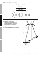
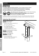
Attaching Post Supports Hardware - 8 each: SAFETY (14) Support Bolt M12 x 50 Threaded Shaft Size (19) Washer M12 (15) Spring Washer M12 (16) Nut M12 ASSEMBLY 1. Using helpers, lift Crane to upright position. Washer (19) 2. Attach Post Supports (5) to Left Base and Post Assemblies using Post Support Bolts (14), Washers (19), Spring Washers (15) and Nuts (16). 3. Tighten connections securely. 4. Repeat for Right Base and Post Assemblies.
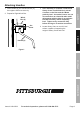
2. Repeat for Right Winch Box. Winch Box (6) Set Screw 3. Once assembly is complete, confirm that Gantry Crane is solid and level, with all 4 casters on the floor and the I-Beam perfectly level. As needed, loosen one set of connections at a time and make small adjustments with the help of an assistant to make the Gantry Crane completely level. Tighten every connection fully before moving on to another connection. 4.
Operation SAFETY TO PREVENT SERIOUS INJURY and DEATH: The use of gantry cranes is subject to certain hazards that cannot be met by mechanical means, but only by the exercise of intelligence, care, common sense, and experience in anticipating the motions that will occur as a result of operating the controls. Wear ANSI-approved safety goggles, hard hat, heavy‑duty work gloves, and steel‑toed work boots during operation. Do not use without Height Pins in place and secured with R-Pins.
Before Operating Hoist WARNING! TO PREVENT SERIOUS INJURY FROM HOIST FAILURE: Do not use damaged equipment. If adjustments or repairs are necessary, or any defects are known, have the problem corrected before further use. 3. Do not operate a hoist with an out-of-order sign. 5. Designate a work area that is clean and well‑lit. The work area must not allow access by children or pets to prevent distraction and injury. SAFETY 2. 4. Only a qualified technician should perform maintenance to the hoist. 6.
WARNING! Follow all safety warnings and instructions for the trolley and hoist you will use with this gantry crane. Additional selected operation points follow: Applying the Load SAFETY TO PREVENT SERIOUS INJURY AND DEATH: Use warning signs and barriers on the floor beneath the gantry crane where overhead maintenance work creates a hazard. Wear ANSI-approved safety goggles, hard hat, heavy‑duty work gloves, and steel‑toed work boots during operation. ASSEMBLY 1.
2. Respond to signals from a designated person only. However, always obey a stop signal, no matter who gives it. 3. Do not lift or lower a load with the hoist until the operator and all other personnel are clear of the load. 4. Make sure the load and hoist will clear all obstacles before moving or rotating the load. 5. Do not lift a load more than a few inches until it is well balanced in the sling or lifting device. 6.
Inspection, Testing, and Maintenance SAFETY Procedures not specifically explained in this manual must be performed only by a qualified technician. TO PREVENT SERIOUS INJURY AND DEATH: Before any inspection, testing or maintenance procedure: 1. Move the gantry crane to a location where it will cause the least interference with other cranes and operations in the area. 2. Park any load that is attached to the gantry crane. ASSEMBLY 3.
1. A gantry crane that has been idle for a period of a month or more, but less than a year, must be inspected before being placed in service according to the Frequent Inspection requirements. 2. A gantry crane that has been idle for a period of a year or more, must be inspected before being placed in service according to the Periodic Inspection requirements, and then tested according to the procedure in the Testing section below. SAFETY Storage Inspection Maintenance 2.
PLEASE READ THE FOLLOWING CAREFULLY SAFETY THE MANUFACTURER AND/OR DISTRIBUTOR HAS PROVIDED THE PARTS LIST AND ASSEMBLY DIAGRAM IN THIS MANUAL AS A REFERENCE TOOL ONLY. NEITHER THE MANUFACTURER OR DISTRIBUTOR MAKES ANY REPRESENTATION OR WARRANTY OF ANY KIND TO THE BUYER THAT HE OR SHE IS QUALIFIED TO MAKE ANY REPAIRS TO THE PRODUCT, OR THAT HE OR SHE IS QUALIFIED TO REPLACE ANY PARTS OF THE PRODUCT.
Record Product’s Serial Number Here: Note: If product has no serial number, record month and year of purchase instead. MAINTENANCE OPERATION ASSEMBLY SAFETY Note: Some parts are listed and shown for illustration purposes only, and are not available individually as replacement parts. Items 41188 69513 For technical questions, please call 1-888-866-5797.
Parts List and Assembly Diagram Parts List SAFETY Part ASSEMBLY 1 2 3 4 5 6 7 8 9a 9b 10 11 12 13 14 Description Post Insert Post Sleeve Base I-Beam Post Support Winch Box Height Pin Handle Swivel Caster Locking Swivel Caster Cable Caster Bolt (M10 x 25) Spring Washer (M10) Nut (M10) Post Support Bolt (M12 x 50) Qty 2 2 2 1 4 2 2 2 2 2 2 16 16 16 8 Part 15 16 17 18 19 20 21 22 23 24 25 26 27 28 29 Description Spring Washer (M12) Nut (M12) Post Bolt (M12 x 110) R-Pin Washer (M12) Pulley Pulley Bolt
SAFETY Assembly Diagram a ASSEMBLY 29 28 MAINTENANCE 29 OPERATION b Items 41188 69513 For technical questions, please call 1-888-866-5797.
Limited 90 Day Warranty Harbor Freight Tools Co. makes every effort to assure that its products meet high quality and durability standards, and warrants to the original purchaser that this product is free from defects in materials and workmanship for the period of 90 days from the date of purchase.