Table of Contents SAFETY Safety.......................................................... 3 Specifications.............................................. 4 Setup........................................................... 4 Operation..................................................... 7 Maintenance................................................ 8 Parts Lists and Diagrams........................... 10 Warranty.....................................................
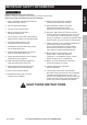
IMPORTANT SAFETY INFORMATION 1. Study, understand, and follow all instructions before operating this device. 14. Keep your work area clean and well lit. Cluttered work areas invite accidents. 2. Do not exceed rated capacity. 15. Keep bystanders, children, and visitors away while operating Engine Crane. Distractions can cause you to lose control. 5. Use only sling or chains with a rated capacity greater than the weight of the load being lifted. 6.
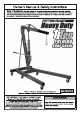
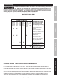
Specifications Ram Capacity Package Contents 3 Ton SAFETY Boom Positions 1 Ton 3/4 Ton 1/2 Ton 1/4 Ton Part 69-5/8" 73-3/4" 77-7/8" 82" Meets 2005 ANSI/ASME PALD standards.
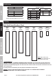
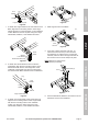
Base Nut Large Caster Legs Figure D Large Caster Bolt (1B) Figure A 1. To attach two Large Casters to the rear section of the Base, align the four mounting holes in each Large Caster with the four mounting holes on the underside of each Base end. Secure in place using four Large Caster Bolts, Washers, Lock Washers and Nuts. 4. Slide Legs into front of the Base. Rear Lock Pin Base Front Lock Pin Small Caster Washer Lock Washer Small Caster Bolt (1B) Figure B 2.
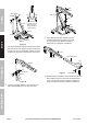
Nut Washer Lock Washer SAFETY Washer Post Nut Leg Leg Bolt (16) Ram Support Bolt (9) The bends of the Supports face out at the top and in at the bottom as shown above. Post Nut Washer Bolt (10) Bolt (9) Supports Figure I Nut Bolt (9) SETUP Washer Lock Washer Figure G 9. Use a Bottom Ram Bolt, Washer and Nut to attach lower end of the Ram to the Post and a Top Ram Bolt, Washer and Nut to attach the top of the Ram to the Boom. 7.
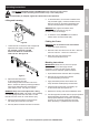
Operating Instructions Read ENTIRE IMPORTANT SAFETY INFORMATION section at beginning of this manual Note: Once Assembly is complete, tighten ALL Bolts before initial operation. 5. To raise the Boom, turn the Ram’s release valve fully clockwise (right). Insert the Handle into the Ram and pump (up and down) repeatedly until the item has been lifted to the desired height. Lifting and Lowering SAFETY including all text under subheadings therein before set up or use of this product.
Maintenance and Servicing Procedures not specifically explained in this manual must be performed only by a qualified technician. SAFETY TO PREVENT SERIOUS INJURY FROM ACCIDENTAL OPERATION: Do not use damaged equipment. If abnormal noise or vibration occurs, have the problem corrected before further use. Cleaning, Maintenance, and Lubrication 1. BEFORE EACH USE, inspect the general condition of the tool.
Troubleshooting TO PREVENT SERIOUS INJURY: Use caution when troubleshooting malfunctioning ram. Stay clear of supported load. Completely resolve all problems before use. If solutions presented in Troubleshooting guide do not solve the problem, have a qualified technician inspect and repair ram before use. After ram is repaired: Test it carefully without a load by raising and lowering it fully, checking for proper operation, BEFORE RETURNING RAM TO OPERATION.
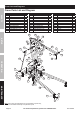
Parts Lists and Diagrams Crane Parts List and Diagram SAFETY Part 1a 1b 2 3 4 5 6 7 8 9 10 Description Qty Large Caster Bolt M8 x 20 16 Small Caster Bolt M8 x 14 8 Washer M8 24 Lock Washer M8 24 Nut M8 16 Lock Pin 110mm 4 Washer M14 6 Lock Washer M14 6 Nut M14 6 Frame Bolt M14 x 100 5 Bottom Ram Bolt M16 x 90 1 Part 11 12 13 14 15 16 17 18 19 20 21 Description Washer M16 Lock Washer M16 Nut M16 Hinge Bolt M18 x 110 Boom Pin 95mm Top Ram Bolt M16 x 80 Nut M18 Lock Washer M18 Washer M18 Chain Bolt M14 x
Part 1A 2A 3A 4A 5A 6A 7A 8A 9A 10A 11A Description Screw O-Ring Spring Ball Cup Steel Ball Screw Cover Release Valve Rectangle Seal Ring Steel Ball Base Pin Qty 1 1 1 1 1 1 1 1 1 1 2 Part 13A 14A 15A 16A 17A 18A 19A 20A 21A 22A 23A Description Pin Shaft Connecting Bar Handle Sleeve Steel Ball Washer O-Ring Shield Ring Pump Core Washer Hydraulic Cylinder Pump Body Qty 2 1 1 2 1 1 1 1 1 1 1 Part 24A 25A 26A 27A 28A 29A 30A 31A 32A Description Seal Ring Oil Tank Oil Plug Rectangle Seal Ring O-Ring Top
Limited 90 Day Warranty Harbor Freight Tools Co. makes every effort to assure that its products meet high quality and durability standards, and warrants to the original purchaser that this product is free from defects in materials and workmanship for the period of 90 days from the date of purchase.