
Product manual


Page 11For technical questions, please call 1-800-444-3353.Item 69434
Part Description
1A Protective Cap
2A Air Cap
3A Nozzle
4A Air Cap Body
5A O-Ring
6A Packing
7A Packing Nut
8A Housing
9A Adjustment Screw
10A Finger Lever
11A Rocker
12A Stopper
13A Needle Chucking Guide
14A Spring
15A Spring Case
16A Needle Chucking Nut
Part Description
17A Handle
18A Needle
19A O-Ring
20A Valve Rod
21A O-Ring
22A Spring
23A Valve Screw
24A Valve Body
25A Hose Connector Nut
26A O-Ring
27A Hose Connector
28A Cup 5cc
29A Wrench 7mm
30A Hanger
31A Glass Jar Assembly 22cc
32A Air Hose (not shown)
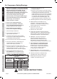
Airbrush Parts List and Assembly Diagram
17
18
4
3
6
2
1
19
9
10
8
11
21
20
22
23
31
28
29
30
5
24
25
26
27
16
7
14
12 13
15
Record Product’s Serial Number Here:
Note: If product has no serial number, record month and year of purchase instead.
Note: Some parts are listed and shown for illustration purposes only,
and are not available individually as replacement parts.
Note: When ordering parts from this assembly diagram,
include the suffix ″A″ after the number.
SAFETYOPERATIONMAINTENANCE SETUP