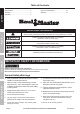
Table of Contents SAFETY Safety.......................................................... 2 Specifications.............................................. 3 Assembly..................................................... 4 Operation..................................................... 6 Maintenance................................................ 8 Parts List and Diagram............................... 10 Warranty.....................................................
14. Before driving vehicle, lower boom and position over truck’s wheel well, then insert Large Lock Pin to prevent boom from swiveling. 15. Attach load to Hook securely by properly rated, suitable means, such as chains, shackles, hooks, lifting slings, etc. Load must be attached to prevent accidental disconnection. 16. Properly seat sling or other device in Hook and fully close Hook’s safety clasp. Do not allow Hook hitch to support any part of load. Do not apply load to the point of the Hook. 17.
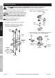
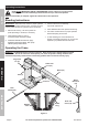
Assembly Instructions Read ENTIRE IMPORTANT SAFETY INFORMATION section at beginning of this manual including all text under subheadings therein before set up or use of this product. SAFETY 1. Locate a mounting position so the Crane will be near end of truck bed and can be attached to frame. 4. Slide Post (7) onto Base (6) and secure using Large Lock Pin (9). (See Figure B.) Post (7) WARNING! The Base must be securely bolted to the frame of the truck bed.
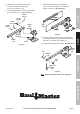
6. Attach Boom (14), Bracket facing down, to Upper Post Bracket using Large Pin (10). and Cotter Pin (11). 8. Slide Boom Extension (15) into Boom so that Oval Hole is facing down. Secure with Small Lock Pin (13). (See Figure E.) Small Pin (12) Boom Extension (15) Upper Post Bracket Cotter Pin (11) Oval Hole Boom Small Lock Pin (13) Figure E Boom Bracket Boom (14) Ram Figure D 9.
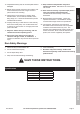
Operating Instructions Read ENTIRE IMPORTANT SAFETY INFORMATION section at beginning of this manual including all text under subheadings therein before set up or use of this product. SAFETY Note: Once Assembly is complete, tighten ALL Bolts before initial operation. Bleeding Instructions IMPORTANT! Before first use, check for proper hydraulic oil level and thoroughly test the Crane. If it does not work properly, bleed air from its hydraulic system as follows: 1. Remove Oil Fill Plug.
WARNING! Engage parking brake before use. Do not move vehicle with load attached to Crane. 4. Attach Hook to properly secured load, giving specific attention to load balancing. 1. Remove Large Lock Pin and swivel Boom so Hook is over load. If necessary, remove Small Lock Pin, adjust Boom Extension, then replace Small Lock Pin. 5. Before lifting load, make sure chain is not kinked or twisted. 6. To lift load: WARNING! Do not attempt to extend or retract Boom while load is attached. a.
Maintenance and Servicing Procedures not specifically explained in this manual must be performed only by a qualified technician. SAFETY TO PREVENT SERIOUS INJURY FROM ACCIDENTAL OPERATION: Do not use damaged equipment. If abnormal noise or vibration occurs, have the problem corrected before further use. Cleaning, Maintenance, and Lubrication 1. BEFORE EACH USE, inspect the general condition of the tool.
Troubleshooting TO PREVENT SERIOUS INJURY: Use caution when troubleshooting malfunctioning Crane. Stay clear of supported load. Completely resolve all problems before use. If solutions presented in Troubleshooting guide do not solve the problem, have a qualified technician inspect and repair Crane before use. After Crane is repaired: Test it carefully without a load by raising and lowering it fully, checking for proper operation, BEFORE RETURNING CRANE TO OPERATION.
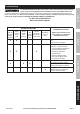
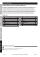
Parts List and Diagram PLEASE READ THE FOLLOWING CAREFULLY SAFETY THE MANUFACTURER AND/OR DISTRIBUTOR HAS PROVIDED THE PARTS LIST AND ASSEMBLY DIAGRAM IN THIS MANUAL AS A REFERENCE TOOL ONLY. NEITHER THE MANUFACTURER OR DISTRIBUTOR MAKES ANY REPRESENTATION OR WARRANTY OF ANY KIND TO THE BUYER THAT HE OR SHE IS QUALIFIED TO MAKE ANY REPAIRS TO THE PRODUCT, OR THAT HE OR SHE IS QUALIFIED TO REPLACE ANY PARTS OF THE PRODUCT.
SAFETY Assembly Diagram 1 11 10 12 15 13 16 17 14 11 SETUP 9 18 8 7 19 20 6 11 5 OPERATION 21 4 3 2 MAINTENANCE 1 Item 60732 For technical questions, please call 1-800-444-3353.
Limited 90 Day Warranty Harbor Freight Tools Co. makes every effort to assure that its products meet high quality and durability standards, and warrants to the original purchaser that this product is free from defects in materials and workmanship for the period of 90 days from the date of purchase.