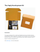
The Haply Development Kit Introduction The Haply development kit is a robust and adaptable open-source hardware development platform for haptic applications. Designed to be accessible to novices and experts alike, the kit allows you to quickly setup and interact with a haptic simulation using a 2degree-of-freedom pantograph device. Visit www.haply.
Kit Overview The Haply development kit contains all the mechanical and electrical components needed to construct your own 2-degree-of-freedom pantograph device. Using the hAPI or Haply API, and with a myriad of example projects and detailed setup tutorials available, the kit allows you to quickly start developing your own haptic applications. With design expansion in mind, the M0 Haply Control Board is capable of controlling up 2 motors.
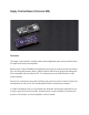
Haply Control Board (Version M0) Overview The Haply control board is a highly robust and configurable open-source platform ideal for haptic and robotic development. Based on the 32-bit ATSAMD21G18 ARM microcontroller, the same used in the Arduino Zero, the Haply M0 features built in USB for Native USB-to-Serial program & debug and fully compatible with the Arduino IDE. For advanced users an SWD interface is also made available.
An optional ATWINC1500 WiFi module may be attached, giving the Haply MO Internet connectivity. This allows for the control of robotics projects over 802.11b,g,n networks with WEP, WPA, and WPA2 encryption. Technical Specifications • Measures 80mm X 32mm x 8mm • ATSAMD21G18 32-bit ARM MCU @48MHz • Native USB port for programming and debugging • 11 GPIO pins • I2C, SPI, and hardware Serial support • 4 analog inputs • Class D amplifier • 2 motor control ports • 3.
Haply Dev Kit Assembly Instructions (V2.0) Haply Development Kit Contents 1. 2. 3. 4. 5. 6. 7. 8. 9. 10. 11. 12. 13.
14. 15. 16. 17. 18. 1x Acrylic plate 1x Board Case Bottom 1x 3D printed Base 1x Haply control Board 1x 3D printed end effector 19.
Part A: Motor Housing Assembly Section parts list: • • • 1x 3D printed motor housing 2x Motors 4x M2 screws 1. Insert the motors into the motor housing with the cable slipped through the gap in the housing. Make sure the motors are pushed all the way to the bottom. 2. Align the holes from the motor housing with the screw holes on the motors and use two M2 screws to fix each motor to the motor housing using a Philips head screwdriver.
Part B: L2 Arm Linkage Assembly Section parts List: • • • 1x Completed assembly from previous section 2x 4-40 set screws 2x 3D printed L1 arm linkages 1. Insert the 4-40 set screws part way into both of the L1 arm linkages. 2. Before attaching the L1 arm linkages to the motors, make sure the flat side of the motor shaft can be aligned with the set screw. 3. Once the motor shafts and the set screws are aligned, attach the arm linkages.
Part C: Motor Stand Assembly Section parts List: • • • • • 1x Completed assembly from previous section 1x 3D printed motor stand 1x Wire adapter board 2x M2 screws black 1x ¾" 4-40 screw 1. Attach the motor cables into the wire adaptor board as shown. 2. Slide the motor stand onto the assembly with the wire adaptor above 3. Insert and tighten the M2 screws into the motor housing.
1. Attach the ¾" 4-40 screw in the front using the flathead screwdriver. The 4-40 screw will go through the motor stand into the small hole on the motor housing.
Part D: L1 Arm Linkage Assembly Section parts List: • • • • 1x Completed assembly from previous section 2x L2 arm linkages 2x Plastic joints assembly 1x End-effector handle assembly 1. Place a plastic joint cap into the L1 arm linkage. 2. Before connecting a L2 arm linkage, make sure a Teflon washer is sandwiched between the two linkages.
1. Install the second L2 arm linkage with a Teflon washer sandwiched between the L1 and L2 arm linkages as pictured. 2. Make sure the second L2 arm is installed on the opposite side compared to the first. 3. On the opposite side of the assembly, place the L1 arm under the L2 arm so that the end of one L2 arm linkage is below the other. This will allow for mounting of the end effector.
1. Place the end-effector cap into the top L2 arm linkage, sandwich the end-effector handle washer between the two L2 arm linkages and finally screw in the end-effector screw to complete this section.
Section parts List: • • • 1x Completed assembly from previous section 2x 2-56 screws 1x Acrylic top plate/ 3D printed base assembly 1. Place the completed assembly into the top plate. 2. Screw the assembly into the top plate on both sides.
Part F: Haply Control Board Installation Section parts List: • • • • • • 1x Completed assembly from previous section 1x Haply control board 2x Dev board extension wires 1x Board Case Top 1x Board Case Bottom 3x 2-56 screws 1. Connect the dev board extension wires to the Haply control board as shown in the picture. 2. Lay the Haply control board inside the case such that the wires extend from the open sides of the case. All motor ports should be accessible.
1. Slide and tighten the case top using the 2-56 screw. Tighten the board to the case bottom using the two other screws. 2. Attach the dev board extension wires as pictured. This will ensure correct function of the Haply software.
PART G: Base Plate Assembly Section parts List: • • • 1x Completed assembly from previous section 1x Acrylic bottom plate 4x Suction cup feet 1. Place the bottom plate and screw in each of the suction cup feet. 2.
Part H: Connectivity Wiring • • 1x Power supply 1x Micro USB cable Although not a part of assembly, the power supply and micro USB cable are attached as shown below The completed Haply Development Kit The Haply project is intended to provide novice designers and developers a platform from which to explore the field of haptics.
Enjoy! Copyright (C) <2017> This program is free software: you can redistribute it and/or modify it under the terms of the GNU General Public License as published by the Free Software Foundation, either version 3 of the License, or (at your option) any later version. This program is distributed in the hope that it will be useful, but WITHOUT ANY WARRANTY; without even the implied warranty of MERCHANTABILITY or FITNESS FOR A PARTICULAR PURPOSE.