
Data Sheet
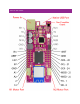
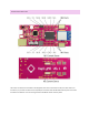

Motor Connection Pins
• M1+ – positive terminal connection for DC motor.
• 5V – connects to the regulated 5V output.
• M1A / 2 – encoder input A, this pin is connected to a set of voltage dividers dropping from a logic level of
5V to 3.3V before reaching GPIO pin 2.
• M1B / 3 – encoder input B, this pin is connected to a set of voltage dividers dropping from a logic level of
5V to 3.3V before reaching GPIO pin 3.
• GND – this is the common ground for all power and logic.
• M1- – negative terminal connection for DC motor.
• M2+ – positive terminal connection for DC motor.
• 5V – connects to the regulated 5V output.
• M2A / A0 – encoder input A, this pin is connected to a set of voltage dividers dropping from a logic level
of 5V to 3.3V before reaching GPIO pin A0.
• M2B / A5 – encoder input B, this pin is connected to a set of voltage dividers dropping from a logic level
of 5V to 3.3V before reaching GPIO pin A5.
• GND – this is the common ground for all power and logic.
• M2- – negative terminal connection for DC motor.
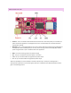
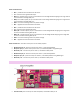
Motor Control Pins – The motor control pins are not directly exposed
• M1 direction pin / 8 – direction control pin for motor 1, controlled by GPIO 8.
• M1 power pin / 9 – power control pin for motor 1, controlled by GPIO 9 using PWM signal.
• M1 Sense / A4 – current sense pin for motor 1, connected to GPIO pin A4.
• M2 direction pin / 6 – direction control pin for motor 2, controlled by GPIO 6.
• M2 power pin / 12 – power control pin for motor 2, controlled by GPIO 12 using PWM signal.
• M2 Sense / A3 – current sense pin for motor 2, connected to GPIO pin A3.
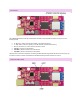
CLASS-D AMPLIFIER
• Class-D control / 11 – Control pin for Class-D amplifier, connected to GPIO pin 11