
Data Sheet
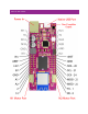
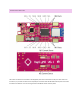

LOGIC PINS
This is the available general purpose I/O pin set for the Haply M0
All logic is 3.3V
All pins can be interrupt inputs
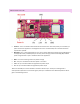
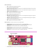
• A1 – This pin is capable of analog input as well as use as a digital I/O pin
• A2 – This pin is capable of analog input as well as use as a digital I/O pin
• 2 – GPIO pin 2
• 13 – GPIO pin 13, this pin is also connected to the yellow LED next to the SWD port
• 20 / SDA – GPIO pin 20, also the I2C (wire) data pin. No pull-up resistor is connected to this pin by default,
please use an appropriate pull-up resistor when connecting a peripheral (usually a 1K – 10K resistor).
• 21 / SCL – GPIO pin 21, also the I2C (wire) clock pin. No pull-up resistor is connected to this pin by default,
please use an appropriate pull-up resistor when connecting a peripheral (usually a 1K – 10K resistor).
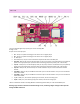
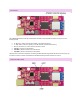
• 24 / SCK – GPIO pin 24, also the clock pin for the SPI interface. This pin is also connected to the WiFi
module.
• 23 / MOSI – GPIO pin 23, also the Master Out Slave In pin for the SPI interface. This pin is also connected
to the WiFi module.
• 22 / MISO – GPIO pin 22, also the Master In Slave Out pin for the SPI interface. This pin is also connected
to the WiFi module.
• 1 / TX – GPIO pin 1, also transmit (output) pin for Serial1, also can be analog input
• 0 / RX – GPIO pin 0, also receive (input) pin for Serial1, also can be analog input
*Note: a mistake was made in the Haply M0 v0.1 PCB markings where GPIO pin 2 was marked GPIO pin 4.
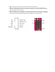
Warning: Logic Pins have a maximum tolerated voltage of 3.3V, connecting a higher voltage to these pins will
damage the MCU and board.