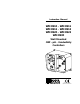
Instruction Manual WM 8910 - WM 8911 WM 8912 - WM 8913 WM 8920 - WM 8923 WM 8930 Wall Mounted ORP - pH - Conductivity Controllers http://www.hannainst.
Dear Customer, Thank you for choosing a Hanna Product. Please read this instruction manual carefully before using the instrument. This manual will provide you with the necessary information for a correct use of the instrument, as well as a more precise idea of its versatility. If you need more technical information, do not hesitate to e-mail us at tech@hannainst.com. These instruments are in compliance with the directives EN 50081-1 and 50082-1. TABLE OF CONTENTS PRELIMINARY EXAMINATION ...................
The recorder output terminals are isolated from the controller circuitry to avoid any interference and are user-switchable between 0 to 20 mA or 4 to 20 mA. These controllers are housed in a rugged, modular, fiber-reinforced polypropylene housing. When in operation, and with the transparent cover installed, the units comply with the IP 54 standards. All available models can be supplied in the 110/115V ("Part No./U") or 220/240V ("/D") version.
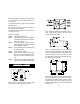
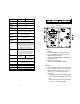
FUNCTIONAL DESCRIPTION WM 8910 SINGLE SETPOINT, p H CONTROLLER FRONT PANEL – Three terminals marked "Out mA Select" to select between 0 to 20 mA or 4 to 20 mA isolated output. 10. Output contacts: – Two terminals marked "°C Sensor" for the connection of a silicon temperature probe for automatic temperature compensation – Two terminals marked "mA Output" for the isolated output BOTTOM CONNECTIONS Left panel 1. LCD display 2. Slope calibration trimmer 3. Coarse setpoint trimmer 4. Fine setpoint trimmer 5.
Specifications WM 8910D WM 8910U 0.00 to 14.00 pH RANGE 0.01 pH RESOLUTION ±0.02 pH ACCURACY (@20°C/68°F) FRONT PANEL TYPICAL EMC DEVIATION ±0.1pH mA OUTPUT User selectable 0 to 20 mA or 4 to 20 mA in a 0-14 pH range with isolated output OFFSET CALIBRATION Through "OFFSET" trimmer (Max. ±1.5 pH regulation) SLOPE CALIBRATION Through "SLOPE" trimmer from 80% to 110% TEMPERATURE COMPENSATION Manual or automatic from -10 to 80°C (14 to 176°F) SETPOINT RANGE From 0.00 to 14.
10. Output contacts: – Two terminals marked "°C Sensor" for the connection of a temperature probe for automatic temperature compensation – Two terminals marked "mA Output" for the isolated output BOTTOM CONNECTIONS 1. BNC socket for a combination pH electrode 2. Input voltage supply socket 3. Output voltage socket for acid dosing (supplies power to a pump or electrovalve). This socket is activated by a relay when the pH is higher than the "SET HI" value. 4.
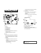
BOTTOM CONNECTIONS FUNCTIONAL DESCRIPTION WM 8912 pH & ORP CONTROLLER FRONT PANEL 1. 2. 3. 4. BNC socket for a combination pH electrode BNC socket for a combination ORP electrode Input voltage supply socket Output voltage socket for pH dosing (activated by a relay when pH is higher than setpoint) 5. Output voltage socket for ORP dosing (activated by a relay when ORP is lower than setpoint) Left panel 1. LCD display for pH measurements 2. Graded dial for setting the pH setpoint (6.00 to 8.00 pH) 3.
BOTTOM CONNECTIONS FUNCTIONAL DESCRIPTION WM 8913 pH & CONDUCTIVITY CONTROLLER FRONT PANEL 1. 2. 3. 4. BNC socket for a combination pH electrode DIN socket (7-pin) for HI 7637 conductivity probe with ATC Input voltage supply socket Output voltage socket for pH dosing (activated by a relay when pH is higher than setpoint) 5. Output voltage socket for conductivity control (closed when the conductivity is higher than setpoint) Left panel 1. LCD display for pH measurements 2.
BOTTOM CONNECTIONS FUNCTIONAL DESCRIPTION WM 8920 SINGLE SETPOINT ORP CONTROLLER FRONT PANEL 1. BNC socket for a combination ORP electrode 2. Input voltage supply socket 3. Output voltage socket (activated by a relay when the measured reading is higher or lower than the setpoint depending on the REDOX/OXYDT selection) Left panel 1. LCD display 2. Slope calibration trimmer 3. Coarse set point trimmer 4. Fine set point trimmer 5. Offset calibration trimmer 6.
BOTTOM CONNECTIONS FUNCTIONAL DESCRIPTION WM 8923 pH & CONDUCTIVITY CONTROLLER FRONT PANEL 1. 2. 3. 4. Left panel 1. LCD display for pH measurements 2. Graded dial for setting the pH setpoint (4.00 to 10.00 pH) 3. LED that lights up when the pH dosage is activated. 4. Offset (pH 7) and Slope (pH 4) calibration trimmers 5. LCD display for conductivity measurements 6. Graded dial for conductivity setpoint (0.50 to 5.00mS/cm) 7. LED that lights up when the conductivity dosage is activated. 8.
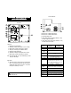
FUNCTIONAL DESCRIPTION WM 8930 CONDUCTIVITY CONTROLLER BOTTOM CONNECTIONS FRONT PANEL 1. DIN socket for HI 7637 conductivity probe 2. Input voltage supply socket 3. Output voltage socket. This socket is activated by a relay when the measured reading is higher or lower than the setpoint depending on the HI/LO selection. Left panel 1. LCD display 2. Slope calibration trimmer 3. Coarse trimmer to adjust the setpoint 4. Fine trimmer to precisely adjust the set-point 5. Offset calibration trimmer 6.
Specifications RANGE WM 8930D WM 8930U 0 to 10,000 µS/cm 1 µS/cm RESOLUTION ACCURACY (@20°C/68°F) ±2% Full Scale TYPICAL EMC DEVIATION ±2% Full Scale mA OUTPUT User selectable 0 to 20 mA or 4 to 20 mA in a 0 to 10000 µS/cm range with isolated output CALIBRATION 2 point through trimmers on the front panel TEMPERATURE COMPENSATION Automatic with ß of 2% per °C SETPOINT RANGE From 0 to 10,000 µS/cm with 2 trimmers: "COARSE" for an approximate regulation and "FINE" for fine tuning.
When activated, the alarm contacts will open or close, triggering the mechanism of your choice, whether a buzzer, light or any other electrical devices (the alarm is a necessity specially with installation in remote locations or when corrective action must be taken immediately). Model Alarm is activated when the reading varies: WM 8910 ±2.0 pH from the setpoint WM 8911 -2.0 pH lower than the SET LO or +2.0 pH higher than the SET HI WM 8912 ±2.
When the meter is in pH dosage mode and the terminals are activated, the DOSE LED will be lit (for WM 8912, WM 8913 and WM 8923 only). pH CALIBRATION (for WM 8910, WM 8911, WM 8912, WM 8913, WM 8923 only) Make sure a combination pH electrode is connected to the BNC socket and the meter is plugged to the mains. Turn the switch to the "MEASURE" position. The calibration should be ideally performed at the temperature of the liquid that is being controlled.
SLOPE ADJUSTMENT: °C 4 cm (1½") • Rinse the electrode thoroughly in water and immerse it in pH 4.01 (HI 7004) or pH 10.01 (HI 7010) buffer solution. Note: Use pH 4.01 if you are going to measure acidic samples or pH 10.01 for alkaline measurements. • Stir the electrode and wait about one minute before adjusting the "SLOPE" or "pH 4" trimmer to display pH 4.01 (or 10.01) on the LCD if the temperature of the buffer solution is at 25°C (77°F).
• Immerse the probe into a beaker with a known calibration solution preferably close to the value of the sample stream (HI 7039L at 5000 µS/cm is recommended for slope calibration). The level of solution must be higher than the holes on the PVC sleeve. • Tap the probe repeatedly on the bottom of the beaker and stir it to ensure that no air bubbles are trapped inside the sleeve. • When the reading stabilizes, turn the "SLOPE" or the "5.
E.g. How to dose base liquids Set point = pH 6.00 Measured value = pH 4.00 To adjust the sample stream to the setpoint, you need to dose base, therefore short "BASE" to the common terminal. Note: • The FINE trimmer can adjust up to ±1.5 pH. • Should you use the WM 8911 for a single-point dosage, it is suggested to adjust the SET LO trimmer to 0.00 pH if you are only dosing acid solutions, and the SET HI to 14.00 pH if you are only dosing basic solutions.
a) mS/cm set point Adjust the graded dial to the desired set point position. The conductivity set point can be set between 0.50 and 3.00 mS/cm. FOR WM 8920 Turn the switch to the "SET" position. The display will show the set value (e.g. mV 650). E.g. How to dose reducing substances Setpoint = mV 650 Measured value = mV 700 To reach the setpoint you need to dose reductants, therefore short "REDOX" with the common (middle) terminal of "CONTROL SELECT". E.g.
FOR WM 8930 Turn the switch to the "SET" position. The display will show the set value (e.g. 5500 µS/cm). Using a small screwdriver, first adjust the setpoint through the COARSE trimmer, then fine tune it to your required level with the FINE trimmer until the desired set value is displayed (e.g. 5000 µS/cm). How to select the dosing direction Select the direction of dosing through the "CONTROL SELECT" terminals.
TAKING REDOX MEASUREMENTS (for WM 8912 and WM 8920 only) Redox measurements allow the quantification of the oxidizing or reducing power of a solution, and are commonly expressed in mV. Oxidation may be defined as the process during which a molecule (or an ion) loses electrons and reduction as the process by which electrons are gained.
ELECTRODE CONDITIONING AND MAINTENANCE These bubbles can be removed by "shaking down" the electrode as you would do with a glass thermometer. If the bulb and/or junction are dry, soak the electrode in HI 70300 Storage Solution for at least one hour. For refillable electrodes**: If the refill solution (electrolyte) is more than 2½ cm (1") below the fill hole, add HI 7082 3.5M KCl Electrolyte Solution for double junction or HI 7071 3.5M KCl+AgCl Electrolyte Solution for single junction electrodes.
For refillable electrodes**: Refill the electrode with fresh electrolyte (HI 7071 for single junction or HI 7082 for double junction electrodes). Allow the electrode to stand upright for 1 hour. Follow the Storage Procedure above. CLEANING PROCEDURE Soak in Hanna HI 7061 General Cleaning Solution for approximately ½ hour. Removal of films, dirt or deposits on the membrane/junction: Protein Soak in Hanna HI 7073 Protein Cleaning Solution for 15 minutes.
MEDIUM DISTANCE, INDOOR/OUTDOOR INSTALLATION When an outdoor installation is required, it is necessary to install a transmitter to obtain accurate readings at distances from 10 to 50 m (33-165'). Since the introduction of AmpHel® these distances are no longer a problem. You can now connect your meter directly to an AmpHel® electrode, saving the cost of a transmitter. The standard cable length of the AmpHel® electrode is 5 m (16.5').
CONDUCTIVITY CALIBRATION SOLUTIONS HI 7030M HI 7030L HI 7031M HI 7031L HI 7039M HI 7039L 12880 µs/cm cal. solution, 230 mL 12880 µs/cm cal. solution, 460 mL 1413 µs/cm cal. solution, 230 mL 1413 µs/cm cal. solution, 460 mL 5000 µs/cm cal. solution, 230 mL 5000 µs/cm cal. solution, 460 mL RECOMMENDED pH ELECTRODES All electrodes are gel-filled and with ceramic junction unless otherwise indicated. HI 1090T Screw connector, external PG13.5 thread, double junction, glass-body PG13.
HI 1135B/3 BNC connector, 3 m (9.9') cable, single junction, refillable with side-arm, glass-body HI 2910B/5 BNC connector, 5 m (16.5') cable, double junction, Ultem®-body with built-in amplifier and cloth junction 3/4 x 16 UNF DIA 12mm M13 x 1.5 DIA 20.5mm DIA 16 mm 38.5mm 25 7 mm mm HI 1115S HI 1135B/3 Screw connector, external PG13.5 thread, double junction, Ultem®-body, cloth junction HI 1210T PG13.5 THREAD φ 12mm 110mm PLATINUM ORP ELECTRODES HI 2930B/5 BNC connector, 5 m (16.
HI 3210T Screw connector, external PG13.5 thread, double junction, Pt, Ultem®-body PG13.5 THREAD CONDUCTIVITY PROBE HI 7637 φ 12mm 6mm DIA 0.23" 30mm 3/4 x 16 UNF DIA 16 mm 7.7mm 0.30" DIA 16 14x0.75 6 125 mm 4.92" DIA 16.5 mm 0.65" DIA 12mm 38.5mm 110mm HI 3410S HI 3430B/3 HI 3932B/5 BNC connector, 5 m (16.5') cable, double junction, Pt, Ultem®-body with built-in amplifier and external thread 3/4 x 16 UNF DIA 12mm DIA 20.5mm 38.5mm 92.5 mm 3.
HI 7855/3 HI 7855/5 HI 8427 HI 8614 HI 8614L HI 8615 HI 8615L HI 8733 HI 9033 HI 931001 MANWMR1 Screw to BNC connector with 3 m (10') cable Screw to BNC connector with 5 m (16.5') cable pH and ORP Electrode Simulator and high impedance tester with 1 m (3.
OTHER PRODUCTS FROM HANNA • • • • • • • • • • • • • • • • • • • • • CE DECLARATION OF CONFORMITY CABLES AND CONNECTORS CALIBRATION AND MAINTENANCE SOLUTIONS CHEMICAL TEST KITS CHLORINE METERS CONDUCTIVITY/TDS METERS DISSOLVED OXYGEN METERS HYGROMETERS ION SPECIFIC METERS (Colorimeters) MAGNETIC STIRRERS Na/NaCl METERS pH/ORP/Na ELECTRODES pH METERS PROBES (DO, µS/cm, RH, T, TDS) PUMPS REAGENTS SOFTWARE THERMOMETERS TITRATORS TRANSMITTERS TURBIDITY METERS Wide Range of Accessories Most Hanna meters are av
POOLS & SPAS WATER ANALYSIS ENVIROCARE GENERAL CATALOG MANWMR1 03/97 These and many others catalogs, handbooks and leaflets are available from Hanna. To receive your free copy, contact your dealer or the nearest Hanna Customer Service Center. PRINTED IN ITALY HANNA LITERATURE h t t p : / / w w w . h a n n a i n s t .