
User Guide

7
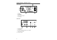
FRONT PANEL
Display
The digital redout indicates the probe current in microamps.
An overcurrent situation (greater than 1.99 µA) results in a
“1.” display (no tenths or hundredths digit). To reduce probe
current, merely reduce probe voltage by pressing the front
panel “ ” key.
Power on indicator
During normal operation the red front panel indicator LED
should be on continuously, indicating that the instrument is
turned on.
Stirrer motor switch
This switch, located on the right hand side of the front panel,
operates the stirrer. Instrument power must be on (LED indi-
cator on) for the stirrer to operate.
“ ” and “ ” bias control keys
Bias voltage applied to the probe is controlled by a digital
potentiometer. The potentiometer has sixty-four steps which
are selected with the front panel “ ” and “ ” keys. A single
depression causes the potentiometer setting to increase or
decrease by one step. Pressing and holding one of the keys
for one second causes the potentiometer to increment or dec-
rement at ten steps per second until the key is released or
until the end of the taper is reached.
A static digital memory retains the last setting when the power
is turned off or removed from the system.
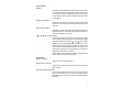
REAR PANEL
Power on switch
To power on and off the instrument.
Probe input connector
The probe is connected to the rear of the instrument with a
BNC connector.
Recorder output connector
The recorder output female connector is located on the rear
panel of the instrument. The recorder connecting cable is
terminated with a male banana type plug provided with the
instrument.