
User Guide


10
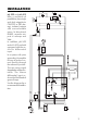
• Power Supply: Connect a 3-wire power cable
to the terminal strip, while paying attention
to the correct line (L), earth (PE) and neu-
tral (N) terminal connections.
Power: 115VAC - 100 mA / 230VAC - 50 mA.
Line Contact: fused inside 400mA.
PE must be connected to ground; leakage current 1mA.
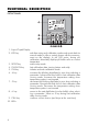
• Electrode: Connect the pH or ORP electrode to the BNC
socket (#10 at page 7).
To benefit from the differential input, connect the proper
electrode wire (if available) or a cable with a potential
matching pin (grounding
bar) to the relevant termi-
nal (#9 at page 7).
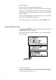
Note When it is not possible to immerse the Potential Matching Pin
together with the pH electrode in the solution, disable the
differential input by connecting the Connection for Potential
Matching Pin (#9 page 7) with the Connection for Electrode
Reference (#8 on page
7) with a jumper wire.
• Pt 100 Terminals: these contacts (#7 at page 7) connect
the Pt 100 temperature sensor for automatic temperature
compensation of pH measurement. In the case of shielded
wire, connect the shield to pin 4.
In the case of a 2-wire sensor con-
nect the Pt 100 to pins 1 and 3,
and short pins 2 and 3 with a
jumper wire.
If the Pt 100 has more than 2
wires, connect the two wires of one
end to pins 2 and 3 (pin 2 is an
auxiliary input to compensate for
the cable resistance) and one wire
from the other end to pin 1. Leave
the fourth wire unconnected, if present.
• Power Supply Output: these terminals
provide +5V and -5V DC signals to
supply power to amplified electrodes.
Note All cables connected to rear panel should end with cable lugs.