PCA 300/PCA 301 Series Panel-mounted, Microprocessor-based Chlorine Analyzers Instruction Manual
Dear Customer, Thank you for choosing a Hanna Product. This instruction manual has been written for the following products: PCA 300 Free Chlorine Analyzer with features such as alarm functions, user-selectable sampling periods, LED warning indications, recorder outputs, RS232 port and a Nema 4X, 12 and 13 enclosure. PCA 301 Total Chlorine Analyzer with features such as alarm functions, userselectable sampling periods, LED warning indications, recorder outputs, RS232 port and a Nema 4X, 12 and 13 enclosure.
START-UP . . . . . . . . . . . . . . . . . . . . . . . . . . . Instrument Power On . . . . . . . . . . . . . . . . Display Brightness . . . . . . . . . . . . . . . . . . Minimum and Maximum Concentration . . . Sampling Rate . . . . . . . . . . . . . . . . . . . . Priming the Reagent System . . . . . . . . . . . ANALYZER PROGRAMMING . . . . . . . . . . . . . Proportional Dosing . . . . . . . . . . . . . . . . Concentration Setpoint Alarm Setting . . . . . Recorder Output Span Setting . . . . . . . . . .
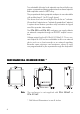
PRELIMINARY EXAMINATION Remove the analyzer from the packing material and examine it carefully to make sure that no damage has occurred during shipping. If there is any noticeable damage, notify your Dealer immediately.
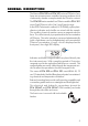
GENERAL DESCRIPTION The Hanna PCA 300 and PCA 301 series of Chlorine Analyzers are microprocessor-controlled, process analyzers which continuously monitor a sample stream for Chlorine content. The PCA 300 series monitor Free Chlorine and the PCA 301 series Total Chlorine in the 0 to 5 mg/L (ppm) range. In the DPD Colorimetric method, N, N-Diethyl-p-phenylenediamine indicator and a buffer are mixed with the sample. The resulting chemical reaction causes a magenta color to form.
Two selectable chlorine level setpoints can be set by the operator: a proportional dosing setpoint and an alarm setpoint. Both setpoints control a SPDT relay. The proportional dosing setpoint analyzers is user-selectable with a delta from 0.1 to 2.0 mg/L (ppm). The alarm level can be set by the user to be an “activateif-lower-than” setpoint or an “activate-if-greater-than” setpoint. A system alarm feature provides relay activation to signal need for operator intervention.
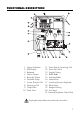
FUNCTIONAL DESCRIPTION 1. 2. 3. 4. 5. 6. 7. 8. 9. 10. Alarms Indicators LED Display Keyboard Alarms Output Recorder Output Peristaltic Pump Access Point to Cell Measuring Cell Output Port Drain Tube 11. Drain Port of Measuring Cell 12. Drain Port Valve 13. Sample Tubing 14. Buffer Bottle 15. Indicator Bottle 16. Sample Port 17. Incoming Pressure Regulator 18. Electrovalve 19. Reagent Tubing 20. Line Input 21. Pressure Regulator Output Port Unplug the meter before any electrical connection.
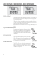
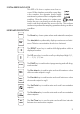
LED DISPLAY, INDICATORS AND KEYBOARD DIGITAL DISPLAY The digital readout will indicate the Chlorine concentration of the last sample measured in milligrams per liter (mg/L) during normal operation. Only when a key is pressed to execute some other function, will the concentration reading be interrupted. In this case, the Chlorine mg/L indicator is turned off. If the Chlorine concentration is above 5 mg/L, the display will blink.
SYSTEM ERROR INDICATOR This LED is lit when a system error has occurred. If the situation persists for more than a few samples, the operator should notify maintenance personnel for investigation of the problem. When the meter is in system error mode, the user can directly access the diagnostic code that indicates the source of error. The analyzer continues to perform the sampling operations during an alarm condition.
SPECIFICATIONS Range PCA 300 PCA 301 0.00 to 5.00 mg/L Free Cl2 0.00 to 5.00 mg/L Total Residual Cl2 Resolution 0.01 mg/L Accuracy ±8% of reading or ±0.05 mg/L whichever is greater Typical EMC Deviation ±0.05 mg/L Minimum detectable level 0.05 mg/L Repeatability ±0.05 mg/L Response time Related to the sampling time selected.
400mg/L for Free Chlorine analysis (PCA 300) or 700mg/L for Total Chlorine analysis (PCA 301) Operating 5 to 40°C (41 to 104°F) temperature range Recorder output Selectable 0-10mV, 0-100mV, 0-1V or 4-20 mA. Output span is settable anywhere in the 0-5 mg/L range Dosage Proportional on one point with a delta adjustable at 0.1, 0.2, 0.3, 0.4, 0.5, 0.6, 0.7, 0.8, 0.9, 1.0, 1.5, 2.
OPERATING DESCRIPTION Referring to the drawing on page 7 and the Fluidic Diagram on page 13, the Sample Line is connected to the instrument at the Sample Port (#16); an internal Regulator (#17) reduces the inlet pressure from a maximum of 4 bar (57.2 psig) down to 1 bar (14.3 psig); from the Regulator a nylon tube is connected to the input of the Electrovalve (#18). The output of the valve goes to the Drain Port (#11 in PCA 300 and PCA 301 only) and then to the Measuring Cell (#8).
Fluid Diagram of the Analyzers METHOD OF ANALYSIS Free available Chlorine (monitored by the PCA300 series) oxidizes the DPD indicator reagent at a pH between 5.5 and 6.0 to form a magenta-colored compound. The intensity of the resulting color is proportional to the concentration of Chlorine in the sample. The purpose of the buffer solution is to maintain the proper pH. To measure Total Residual Chlorine (Free available Chlorine plus combined Chloramines) the PCA301 series adds Potassium Iodide.
INITIAL PREPARATION AND INSTALLATION INSTALLATION PERSONNEL Installation of the PCA 300 and PCA 301 family of Chlorine Analyzers should be undertaken by persons with technical knowledge of the dangers associated with chemical exposure and electrical shock. Hanna Instruments assumes persons performing the installation tasks are aware of the appropriate safety procedures. Review the Material Safety Data Sheets (MSDS) before handling the supplied chemical reagents.
Direct routing of sample lines is also recommended. If the large process pipes are horizontal, taps should be inserted vertically in the middle of the pipe to avoid pulling sediment from the bottom or air bubbles from the top of the pipe into the sample line. A 1/2” BSP sample input fitting allows direct connection to the optional input filter. Sample line pressure should be between 0.07 and 4 bar (1 and 57.2 psig) with an ideal pressure of 0.7 bar (10 psig).
Return Line Installation The return hose fitting is a 12 mm (1/2”) hose barb on the bottom of the regulator output port and should always be connected even when pressure is below 1 bar. INSTALLING THE INPUT FILTER In order to ensure maximum accuracy of measurements, it is recommended to have always clear sample, with suspended particles smaller than 0.5 µm. This can be achieved by installing two filters before the sample input.
Grasp the other plastic collar and pull, stretching the center section, and place the grommet in the lower left indentation hole. Repeat this process with the second pump tube, placing it in the upper indentation holes. Separate reagent caps are provided in the accessory kit. Put the supplied caps onto each reagent bottle prior to installing them.
ELECTRICAL CONNECTIONS A power cable (3 mt.) is provided with your analyzer. However, if access to the terminal block is required, see below. Warning Electrical connections should be installed only by qualified personnel to assure conformity to applicable electrical codes. Unplug the meter before any electrical connection. Power Power connections are made at a terminal block located in the center of the electrical compartment to the right of the fuses.
Recorder Output and Relay Access Hard wiring for alarms and relays can be accomplished through four watertight connectors on the left of the enclosure, by passing wires through the rubber grommet and tightening the nut as described earlier. Refer to the drawing on the right for proper wire connections. Alarm System A system alarm feature provides relay activation to signal need for operator intervention through an external device, such as a buzzer, a light or any other electrical equipment.
Recorder Output Recorder output connections are made as indicated on the picture aside. The control panel must be opened. A wiring access hole is located on the left side of the instrument case. Use two wire shielded cable with the shield connected at the analyzer end only. This wire access hole should be used only for recorder or serial I/O cables (low voltage). Recorder The recommended recorder hookup uses a Output shielded, twisted-pair cable.
Set the individual micro-switch for the desired output in the ON position (e.g. 0-1V). See table below. Switch Function 6 Not used 5 Calibrate Current 4 4 - 20 mA 3 0 -1 V 2 0 -100 mV 1 0 -10 mV Dosing Pump Proportional dosing can be performed connecting an external pump to the DOSING RELAY block terminal. For the correct connection, see the drawing aside.
START-UP INSTRUMENT POWER ON When the POWER switch is turned on or RESET is pressed, the moving words “Hanna PCA300” will appear. This display will continue for 20 seconds. RESET Then the concentration is set to 0.00 mg/L. An indication appropriate to the key pressed or, after 5 minutes, the first mg/L reading will appear on the display. Note The SYS.ERROR LED and relay will not activate before the first reading. Be sure the sample stream is open and flowing through the system.
• Enter code 700 using the and keys. • Press DIAG and “brt” will be displayed. Then the brightness of the display will begin to change through the three levels. DIAG • Press DIAG at one of the 3 brightness level and the analyzer will store that brightness level. If DIAG is not pressed, the brightness will remain at the present level. DIAG MINIMUM AND MAXIMUM CONCENTRATION In any moment it is possible to recall the current minimum and maximum chlorine values taken since the last reset.
Press DIAG. “0.00” will appear on the display and the two levels will be set to the current value. DIAG SAMPLING RATE The sampling rate is user-selectable from a minimum of a measurement every 5 minutes to a maximum of one every 90 minutes. It is possible to recall and change the interval between two different measurements at any given moment. Simply press SET TIME. SET TIME Select the desired interval between 5 and 90 using the and keys.
PRIMING THE REAGENT SYSTEM A special diagnostic function included in the software provides a convenient way to prime the peristaltic pump and reagent tubing during initial start-up. This decreases the time needed for instrument stabilization to about three minutes or until DIAG is pressed again. 1. Press DIAG. The display will show the last diagnostic mode and the right-most numerical digit will blink. DIAG 2. Enter priming code 502 using the and keys. 3. Press DIAG to execute priming sequence.
ANALYZER PROGRAMMING When power is first applied to the analyzer, programmable parameters of the analyzer are set to default values established at the factory. These values or any new values entered by the operator are stored in nonvolatile EEPROM which will retain the programmed values in the event of power failure. All programmable parameters are viewed or adjusted via dedicated push buttons.
• Press SETPOINT twice to store the new setpoint. • To set the range within which the proportional dosing occurs (delta), press DIAG. The display will show the last diagnostic mode and the right-most numerical digit will blink. DIAG • Enter code 400 using the and keys. • Press DIAG and the possible settings, 0.1, 0.2, 0.3, 0.4, 0.5, 0.6, 0.7, 0.8, 0.9, 1.0, 1.5, 2.0, will scroll. DIAG Note If the analyzer has been reset or turned on, “0.1” is the default delta. • Store the desired delta, e.g. 0.
Example With the previously given values, sample rate 5 minutes and measured value 2.8 mg/L, the proportional dosing will be active for the initial 2 minutes and will stop for the remaining 3 minutes. In fact: 0.5 mg/L : 5 min = 0.2 mg/L (3-2.8) : X then X = 2 minutes. CONCENTRATION SETPOINT ALARM SETTING PCA 300 and PCA 301 are equipped with a fully programmable concentration alarm that will activate an indication when the chlorine concentration limit is exceeded.
• Enter code 710 using the and keys. • Press DIAG and the display will scroll through “AL —”, maximum desired level, and “AL —”, minimum desired level. DIAG DIAG • Press DIAG when the needed condition appears. • To see the current alarm logic (high or low alarm), press DIAG. The display will show the last diagnostic mode and the right-most numerical digit will blink. DIAG • Enter code 711 using the and keys.
• When an alarm condition is met, the ALARM LED turns on and the corresponding relays closes. RECORDER OUTPUT SPAN SETTING The selected recorder output voltage range or the 4-20 mA current output may be associated with any Chlorine concentration in the 0 to 5 mg/L range. For example, if the 0.0 to 1.0 V recorder output has been selected, the operator can select 0.0 V to correspond to a concentration of 3.0 mg/L (Recorder Minimum setting) and 1.0 V to correspond to a concentration of 4.
• If you want to store the new setpoint promptly press REC.MIN again. Display will show “Stor” for a short time indicating that the new setpoint is stored and will return to the Chlorine concentration display. REC. MIN • If you do not want to change the setpoint, do not press REC.MIN a second time. The display will return to the Chlorine concentration display and the setpoint will not be changed. To set the higher limit of the recorder output • Press REC.MAX.
• If you want to store the new setpoint, promptly press REC.MAX again. Display will show “Stor” for a short time indicating that new setpoint is stored and will return to the Chlorine concentration display. REC. MAX • If you do not want to change the setpoint, do not press REC.MAX a second time. The display will return to the Chlorine concentration display and the setpoint will not be changed.
voltage limits can be calibrated automatically as follows: 1.A To automatically calibrate "ZERO" scale 1.A.1 Press DIAG. The display will show the last diagnostic mode and the right-most numerical digit will blink. DIAG Note If the analyzer has been reset or turned on, “d000” will appear when pressing DIAG. 1.A.2 Enter code 104 using the and keys. 1.A.3 Press DIAG; “rc 0” will be displayed and the analyzer will execute this mode. DIAG 1.B To automatically calibrate "FULL" scale 1.B.1 Press DIAG.
1.B.3 Press DIAG; “rc 1” will be displayed and the analyzer will execute this mode calibrating the span value e.g. 1V, 10mV or 100mV. DIAG Microprocessor programming routines will measure and calibrate the output limits. This procedure will set the output to approximately 1% accuracy. Fine tune the recorder output by following the procedure in step 3.
2.A.4 Press DIAG; “rc 4” will be displayed and the analyzer will execute this mode calibrating the output to 4 mA. DIAG 2.B To automatically calibrate "20 mA" 2.B.1 Press DIAG. The display will show the last diagnostic mode and the right-most numerical digit will blink. DIAG 2.B.2 Enter code 107 using the and keys. 2.B.3 Press DIAG; “rc20” will be displayed and the analyzer will execute this mode calibrating the output to 20 mA. DIAG 2.B.
This procedure will set the output to 1%. Fine tune the recorder output by following the procedure in step 3. Step 3 Recorder If the recorder output needs fine tuning, use Output the diagnostic routines described below. • Set the DIP switch to the desired option: 0-10mV/100mV/1V or 4-20 mA.
DIAG 3.A.4 The reading on multimeter will slowly increase. When the desired value is reached, press DIAG again to store it and quit the mode. DIAG 3.B If the recorder zero reads too high 3.B.1 Press DIAG. The display will show the last diagnostic mode and the right-most numerical digit will blink. DIAG 3.B.2 Enter code 101 using the and keys. After code is selected display will show “d101”. 3.B.
3.C If the recorder full scale (upper limit) reads too low 3.C.1 Press DIAG. The display will show the last diagnostic mode and the right-most numerical digit will blink. DIAG 3.C.2 Enter code 102 using the and keys. 3.C.3 Press DIAG; “r up” will be displayed and the analyzer will execute this mode fine tuning upper value. DIAG DIAG 3.C.4 The reading on multimeter will slowly increase. When the desired value is reached, press DIAG again to store it and quit the mode. 3.
3.D.2 Enter code 103 using the and keys. 3.D.3 Press DIAG; “r dn” will be displayed and the analyzer will execute this mode fine tuning upper value. DIAG 3.D.4 The reading on multimeter will slowly decrease. When the desired value is reached, press DIAG again to store it and quit the mode.
RECORDER OUTPUT LIMITS CHECK At any time, it is possible to see on a multimeter the present settings of the recorder output, e.g. 0-1mV, 4-20 mA etc. This feature is particularly useful to check Recorder the settings and to ensure the outputs are Output functioning. • Set the DIP switch to the desired option: 0-10mV/100mV/1V or 4-20 mA.
1.D and the multimeter will display the current minimum recorder output limit. Press DIAG again to quit the mode. DIAG DIAG To see the current maximum recorder output limit 2.A Press DIAG. The display will show the last diagnostic mode and the right-most numerical digit will blink. DIAG 2.B Enter code 111 using the and keys. 2.C Press DIAG; “— —” will be displayed and the analyzer and the multimeter will display the current maximum recorder output limit. DIAG DIAG 2.
3.B Enter code 112 using the and keys. 3.C Press DIAG; “– –” will be displayed and the analyzer and the multimeter will display the current mid-range recorder output limit. DIAG DIAG 3.D Press DIAG again to quit the mode. ADJUSTING THE LIGHT SOURCE If the sample blank is highly colored or turbid, the light level may be inadequate for a proper operation. This situation is indicated by the activation of the analyzer system alarm relay and the appearance of “E09” on the display.
To adjust the light level of the blank sample: 1. Press DIAG. The display will show the last diagnostic mode and the right-most numerical digit will blink. DIAG 2. Enter code 999 using the and keys. After the code is selected display will show “d999”. 3. Press DIAG to execute the light level set mode. All the display digits will blink. DIAG 4. The display will show direct reading of the photodetector cell. 5. Make sure the photometric chamber is well flushed.
MAINTENANCE CALIBRATION REQUIREMENT Calibration of the PCA 300 and PCA 301 series of Chlorine Analyzers is not normally required. The DPD technique for measuring Chlorine concentration is well established and consistent. Also, by measuring the sample blank absorbancy to establish the zero reference with each measurement, the accuracy of the analyzer is assured. If, for any reason, the Chlorine measurements are inaccurate proceed with the calibration procedure (see page 48).
To see the current value, press DIAG. The display will show the last diagnostic mode and the right-most numerical digit will blink. DIAG Enter code 701 using the and keys. Press DIAG and the number of measurements taken will be displayed in tens (e.g. 8363 will be displayed as 836). DIAG To reset the counter, press DIAG. The display will show the last diagnostic mode and the right-most numerical digit will blink. DIAG Enter code 702 using the and keys.
Once reagents are completely exhausted, the system error LED will lit (while the relay remains activated) to notify the user. CHANGING PERISTALTIC PUMP TUBING It is recommended that the peristaltic pump tubes be changed on a regular basis depending on sampling period and operating time. For a 5 minutes sample interval and continuous operation, changing of the tubes every month is recommended. For best results however, change the tubings every time the reagents are replaced.
TUBING REPLACEMENT The remaining tubing in the analyzers should be replaced every two months. When installing new tubing it is helpful to dip them in hot water before making the connections. It is also recommended that one tube at a time is removed and replaced. Note DPD reagent tubing may darken before the scheduled replacement time, but this will not affect the instrument’s performance.
RELAY TEST In the relay test mode all three alarm relays close for about one second. 1. Press DIAG . The display will show the last diagnostic mode and the right-most numerical digit will blink. DIAG 2. Enter code 501 using the and keys. After the code is selected display will show “d501”. 3. Press DIAG. The display will blink “ON” and “OFF”, then the display will automatically return to the last concentration reading. CALIBRATION PROCEDURE 1.
3. Wait for the PCA to display the reading. 4. Press DIAG. The display will show the last diagnostic mode and the right-most numerical digit will blink. DIAG 5. Enter code 900 using the and keys and press DIAG. DIAG 6. Enter the calibration value using the and keys. 7. Press DIAG to confirm the value. The display will show “Stor” for a short time indicating that the new calibration value is stored. The unit will return to normal operation displaying the calibrated value.
ERROR CODES ERROR 0 - NO ERROR ERROR 1- INVALID LOW-SCALE ADJUSTMENT OF RECORDER OUTPUT 1. The manual (fine) low-scale adjustment of the recorder output in the DOWN direction (DIAG 101) could not be performed. 2. The automatic low-scale adjustment of the recorder output in the DOWN direction (DIAG 104 or 106) could not be performed. Check the dip switches for proper configuration. Also, when in DIAG 101, “E01” can occur if the user does not press DIAG again before the displayed DVM reading goes below: a.
Check the dip switches for proper configuration. Also, when in DIAG 100, “E03” can occur if the user does not press DIAG again before the displayed DVM reading goes above: a. 100 mV, with 0-1 V dip switch setting b. 10 mV, with 0-100 mV dip switch setting c. 1 mV, with 0-10 mV dip switch setting. Another possibility is hardware failure.
ERROR 8 - LOW ABSORPTION The measured absorption is too low. Possible reasons include: 1. empty reagent bottles; 2. clogged, pinched or broken tubes; 3. interrupted sample flow. ERROR 9 - LOW BLANK READING If the sample blank is highly colored or turbid, the light level may be inadequate for a proper operation. This situation is indicated by the activation of the analyzer system alarm relay and the appearance of “E09” on the display. This condition can also be caused by failure of the LED light source.
OPERATIONAL & DIAGNOSTIC CODES Code 100 101 102 103 104 105 106 107 110 111 112 400 401 500 501 502 Function Increase recorder output lower limit in manual low-scale adjustment Decrease recorder output lower limit in manual low-scale adjustment Increase recorder output upper limit in manual full-scale adjustment Decrease recorder output upper limit in manual full-scale adjustment Set recorder 0 V automatically with dip switch setting at 0-1 V, 0-100 mV or 0-10 mV Set recorder full-scale automatically w
503 700 701 702 710 711 800 900* 901* 902* 999 * 54 Clear previous minimum/maximum concentration values Set the display brightness level Show the current reagent counter value (in tens) Reset the reagent counter Set the alarm logic (low or high) Show the current alarm logic Show the last system error message (E08 to E10) Show the current value and allow calibration to a new value Show the calibration factor (0.00 to 1.00) Reset the calibration factor to 1.
INTERFACE WITH PC (PCA 300 and PCA 301 only) A serial interface permits the PCA 300 and PCA 301 to have direct connection with a computer. Connection with a computer allows collecting, storing or printing of the sample concentration data. Data transmission from the instruments to the PC is possible with the HI92000 Windows® compatible application software offered by Hanna Instruments. Refer to the drawing for proper wire connections.
ACCESSORIES ChecktempC HI 70473 HI 70474 HI 70475 HI 70476 HI 70477 HI 70478 HI 70479 HI 70480 HI 70481 HI 70482 HI 70483 HI 70484 HI 70485 HI 70486 HI 70487 HI 70488 HI 70489 HI 92000 56 Termometer (-50.0 to 150.
WARRANTY All Hanna Instruments meters are guaranteed for two years against defects in workmanship and materials when used for their intended purpose and maintained according to instructions. This warranty is limited to repair or replacement free of charge. Damage due to accident, misuse, tampering or lack of prescribed maintenance are not covered. If service is required, contact the dealer from whom you purchased the instrument.
OTHER PRODUCTS FROM HANNA • • • • • • • • • • • • • • • • • • • • CALIBRATION AND MAINTENANCE SOLUTIONS CHEMICAL TEST KITS CHLORINE METERS CONDUCTIVITY/TDS METERS DISSOLVED OXYGEN METERS HYGROMETERS ION SPECIFIC METERS (Colorimeters) MAGNETIC STIRRERS Na/NaCl METERS pH/ORP/Na ELECTRODES pH METERS PROBES (DO, µS/cm, RH, T, TDS) PUMPS REAGENTS SOFTWARE THERMOMETERS TITRATORS TRANSMITTERS TURBIDITY METERS Wide Range of Accessories Most Hanna meters are available in the following formats: • BENCH-TOP METERS •
CE DECLARATION OF CONFORMITY Recommendations for Users Before using these products, make sure that they are entirely suitable for the environment in which they are used. Operation of these instruments in residential areas could cause unacceptable interference to radio and TV equipment. Any variation introduced by the user to the supplied equipment may degrade the instruments' EMC performance. Unplug the instruments from power supply before opening the front cover.
PCA300 AND PCA301 COMPLIANCE MARKS MANPCA300R1 07/02 w w w . h a n n a i n s t .