pH 500 & mV 600 Series Panel-mounted, Microprocessor-based pH and ORP Controllers Instruction Manual
Dear Customer, Thank you for choosing a HANNA product.
PRELIMINARY EXAMINATION Remove the instrument from the packing material and examine it carefully to make sure that no damage has occurred during shipping. If there is any noticeable damage, notify your Dealer or the nearest Hanna Customer Service Center immediately. Note Save all packing materials until you are sure that the instrument functions correctly. Any damaged or defective items must be returned in their original packing materials together with the supplied accessories.
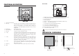
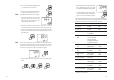
FUNCTIONAL DESCRIPTION REAR PANEL FRONT PANEL 1. Liquid Crystal Display 2. LCD key exits from setup and calibration modes and reverts back to normal mode (in idle or control phases with the measurement on the display). In pH 500 series, during pH calibration, alternately displays pH buffer value or current temperature 3. SETUP key enters setup mode 4. CAL DATA key last calibration data viewing (enters and exits) 5. CAL key initiates and exits calibration mode 6.
SPECIFICATIONS pH 500 & mV 600 Range 0.00 to 14.00 pH ±2000 mV -9.9 to 120.0 °C Resolution 0.01 pH 1 mV 0.1 °C Accuracy ±0.02 pH (pH 500 series only) ±2 mV (mV 600 series only) ±0.5 °C (@20°C/68°F) (pH 500 series only) (mV 600 series only) (pH 500 series only) (mV 600 series only) Typical EMC Deviation ±0.2 pH (pH 500 series only) ±10 mV (mV 600 series only) ±0.5 °C Calibration pH: automatic, 1, 2 or 3 point, at pH 4.01, 7.01, 10.
• Power Supply: Connect a 3-wire power cable to the terminal strip, while paying attention to the correct line (L), earth (PE) and neutral (N) terminal connections. Power: 115VAC - 100 mA / 230VAC - 50 mA Line Contact: fused inside 400 mA. PE must be connected to ground; leakage current 1mA. • Electrode: Connect the pH or ORP electrode to the BNC socket (#10 at page 7).
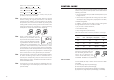
• Then confirm the displayed digit with and move to the next one. • When the whole password has been inserted, press CFM to confirm it. Note The default password is set at “0000”. • The LCD will display “SET” on the upper part and “c.00” on the lower, allowing the user to edit setup parameters (see table below). • Enter the code of the parameter you want to set, using the arrow keys as per the password procedure above (e.g.41).
Code PW Code Valid Values Default PW 30 Relay 3 high alarm (HA) 0.00 to 14.00 pH 9.00 pH -2000 to 2000 mV 600 mV HA>LA, HA>S1 or HA>S2 no 91 Keyboard selftest 0: off 1: on 0 yes 92 EEPROM selftest yes 0.00 to 14.00 pH 5.
then S1–H1>S2, S2–D2>LA, HA>S1; If M1 = 3 and M2 = 4 then S1>S2, S2–D2>LA, HA>S1+D1; If M1 = 4 and M2 = 3 then S2>S1, S1–D1>LA, HA>S2+D2; where the minimum deviation (D1 or D2) is 0.5 pH (for pH 500) or 25 mV (for mV 600). Note The password cannot be viewed when SETUP is pressed without entering the original password first. The default password is set at “0000”.
An upper boundary is imposed for acid/base dosage time when relays are energized continuously, i.e. when relay works in ON/OFF mode or in proportional mode but in the latter case only if the relay is always ON. This parameter can be set through setup procedure. When the maximum boundary is reached, an alarm is generated; device stays in alarm condition until relay is de-energized.
• ALWAYS OFF if pH > setpoint; In addition to the user-selectable alarm relays, all pH 500 and mV 600 models are equipped with the Fail Safe alarm feature. The Fail Safe feature protects the process against critical errors arising from power interruptions, surges and human errors. This sophisticated yet easy-to-use system resolves these predicaments on two fronts: hardware and software.
IDLE MODE ANALOG OUTPUT During idle mode the device performs the same tasks as when it is in control mode except for the relays. The alarm relay is activated (no alarm condition), the acid and base relays are not activated while the analog output remains activated. When the instrument is in idle mode the red and green status LEDs are on. Idle mode is useful to disable control actions when the exter- All models pH 500XY1 and mV 600XY1 are provided with the analog output feature.
These values can be changed by the user to have the analog output matches a different pH range, for example, 4 mA = 3.00 pH and 20 mA = 5.00 pH. To change the default values, the setup mode must be entered. Setup codes for changing the analog output minimum and maximum are 41 or 42, respectively. For the exact procedure, refer to the setup mode section in the manual. Note The difference between maximum and minimum values for the analog output must be at least 1.00 pH or 50 mV.
Cables other than HI 920010 may use a different configuration. In these cases, no communication between the meter and the PC is possible.
For accurate calibration, use two beakers for each buffer solution, the first one for rinsing the electrode, the second one for calibration. By doing this, contamination between the buffers is minimized. RINSE CALIBRATION HI 7007 HI 7007 To obtain accurate readings, use pH 7.01 and pH 4.01 if you measure acidic samples, or pH 7.01 and pH 10.01 for alkaline measurements or perform a 3-point calibration for the entire range.
Two-point Calibration • Proceed as described above for one-point calibration, using pH 7.01 as the first point, but do not quit calibration by pressing CAL at the end. Note Three-point Calibration • Proceed as described above but do not quit calibration by pressing CAL. Note The meter will automatically skip the buffer that was used for the first calibration to prevent errors.
CALIBRATION WITH MANUAL TEMPERATURE COMPENSATION • Enter the calibration procedure and press LCD to display the temperature on the secondary LCD. • Unplug any temperature probe that may be attached to the meter. The "°C" symbol will flash. • Note the temperature of the buffer solutions with a ChecktempC or an accurate thermometer with a resolution of 0.1°C. • Use or to manually adjust the display reading to the value of the reference thermometer (e.g. 20°C).
• When the reading has stabilized at a point near the first calibration point, CAL will stop blinking and an intermittent CFM icon will prompt the user to confirm the first calibration. • If the display stabilizes at a value significantly different from the first setpoint, an intermittent WRONG icon will prompt the user to check and adjust the simulator and start again. • After pressing CFM the unit will switch to the second calibration point at 350 mV.
°C • Immerse the temperature probe in the second beaker as near to the Checktemp as possible and repeat the above procedure. • Press CFM to confirm the selected parameter that will stop blinking on the primary display. The secondary display shows the HI 931002 or multimeter input value as lower limit of the interval. 50 °C (122 °F) Calibration procedure may be interrupted by pressing CAL again at any time.
OUTPUT TYPE CALIBRATION CODE CALIBRATION POINT 1 CALIBRATION POINT 2 0-1 mA 0 0 mA 1 mA 0-20 mA 1 0 mA 20 mA 4-20 mA 2 4 mA 20 mA 0-5 Vdc 3 0 Vdc 5 Vdc 1-5 Vdc 4 1 Vdc 5 Vdc 0-10 Vdc 5 0 Vdc 10 Vdc LAST CALIBRATION DATA The meter stores the following information about last calibration in the EEPROM: • Date • Time • Offset in mV (for pH 500 only) • Up to two slopes (for pH 500 only) • Up to three buffers While displaying this data, the pH controller remains in control mode.
Note In any moment, by pressing LCD or CAL DATA the meter will return to the regular operating display. • Press or to view the time of last calibration. The secondary display will show "HOU" to indicate hours. • Press or again to view the offset in mV at the time of last calibration. The secondary display will show "OFF" to indicate offset. • Press or again to view the second memorized buffer at the time of last calibration. The secondary display will show "BUF2" to indicate second buffer.
STARTUP FAULT CONDITIONS AND SELFTEST PROCEDURES At startup the firmware release code scrolls through the LCD; it is possible to escape from code scrolling pressing any key. During the automatic startup the Real Time Clock (RTC) is checked to see if a reset occurred since last software initialization. In this case, the RTC is initialized with the default date and time 01/01/1997 - 00:00. An EEPROM reset does not affect the RTC settings. The EEPROM is also checked to see if it is new.
The error detection for dead loops is performed by watchdog (see below). You can use special setup codes, perform selftest procedures for LCD, keyboard, EEPROM, relays and LEDs, watchdog. The operation of these functions is outlined in the setup section. The selftest procedures are described in detail in the following subsections. The colon is a useful indicator for the correct position of squares. Note A maximum of two keys may be pressed simultaneously to be properly recognized.
RELAYS AND LEDS pH VALUES AT VARIOUS TEMPERATURES Relays and LEDs selftests are executed as follows: First all of the relays and LEDs are switched off, then they are switched on one at a time for a few seconds and cyclically. User can interrupt the otherwise endless cycle, as indicated by the scrolling message, by pressing a key. Note Relays and LEDs test has to be carried out with the relay contacts disconnected from external plant devices.
ELECTRODE CONDITIONING AND MAINTENANCE If the bulb and/or junction are dry, soak the electrode in HI70300 storage solution for at least one hour. For refillable electrodes**: If the refill solution (electrolyte) is more than 2½ cm (1") below the fill hole, add HI 7082 3.5M KCl electrolyte solution for double junction or HI 7071 3.5M KCl+AgCl electrolyte solution for single junction electrodes.
• No Slope: - Check the electrode for cracks in glass stem or bulb (replace the electrode if cracks are found). - Make sure cable and connections are not damaged nor lying in a pool of water or solution. • Slow Response/Excessive Drift: soak the tip in the HI 7061 solution for 30 minutes, rinse thoroughly in distilled water and then follow the Cleaning Procedure above.
TAKING REDOX MEASUREMENTS Redox measurements allow the quantification of the oxidizing or reducing power of a solution, and are commonly expressed in mV. Oxidation may be defined as the process during which a molecule (or an ion) loses electrons and reduction as the process by which electrons are gained. Oxidation is always coupled together with reduction so that as one element gets oxidized, the other is automatically reduced, therefore the term oxidation-reduction is frequently used.
ACCESSORIES pH CALIBRATION SOLUTIONS HI 7004M pH 4.01 buffer solution, 230 mL bottle HI 7004L pH 4.01 buffer solution, 500 mL bottle HI 7004/L pH 4.01 buffer solution, 1 L bottle HI 7007M pH 7.01 buffer solution, 230 mL bottle HI 7007L pH 7.01 buffer solution, 500 mL bottle HI 7007/L pH 7.01 buffer solution, 1 L bottle HI 7010M pH 10.01 buffer solution, 230 mL bottle HI 7010L pH 10.01 buffer solution, 500 mL bottle HI 7010/L pH 10.
PLATINUM ORP ELECTRODES HI 3090T Screw connector, external PG13.5 thread, double junction, Pt, glass body, polymer filled HI 3210B/5 HI 3210T BNC connector, 5 m (16.5') cable, double junction, Pt, plastic body, PVDF junction, polymer-filled Screw connector, external PG13.5 thread, double junction, Pt, plastic body, cloth junction GOLD ORP ELECTRODES HI 4932B/5 BNC connector, 5 m (16.
ORP ELECTRODES ½‘’ thread, double PVDF junction, polymer filled, max operating pressure of 6 bar (87 psi) PLATINUM ELECTRODES Part Code HI 2002/3 Matching Pin NO Amplifier Connector Cable NO BNC 3 m (10’) HI 2002/5 NO NO BNC 5 m (16.5’) HI 2003/3 YES NO BNC* 3 m (10’) HI 2003/5 YES NO BNC* 5 m (16.5’) HI 2004/5 YES YES spade lugs* 5 m (16.5’) Amplifier Connector Cable OTHER ACCESSORIES BL PUMPS Dosing pumps with flow rate from 1.
WARRANTY OTHER PRODUCTS FROM HANNA All Hanna Instruments meters are guaranteed for two years against defects in workmanship and materials when used for their intended purpose and maintained according to instructions. The electrodes and the probes are guaranteed for a period of six months. This warranty is limited to repair or replacement free of charge. Damage due to accident, misuse, tampering or lack of prescribed maintenance are not covered.
CE DECLARATION OF CONFORMITY HANNA LITERATURE Hanna publishes a wide range of catalogs and handbooks for an equally wide range of applications. The reference literature currently covers areas such as: • • • • • • • Water Treatment Process Swimming Pools Agriculture Food Laboratory Thermometry and many others. New reference material is constantly being added to the library. For these and others catalogs, handbooks and leaflets, contact your dealer or the Hanna Customer Service Center nearest to you.
TECHNICAL SERVICE CONTACTS Australia: Tel. (03) 9769.0666 • Fax (03) 9769.0699 China: Tel. (10) 88570068 • Fax (10) 88570060 Egypt: Tel. & Fax (02) 2758.683 Germany: Tel. (07851) 9129-0 • Fax (07851) 9129-99 Greece: Tel. (210) 823.5192 • Fax (210) 884.0210 Indonesia: Tel. (21) 4584.2941 • Fax (21) 4584.2942 Japan: Tel. (03) 3258.9565 • Fax (03) 3258.9567 Korea: Tel. (02) 2278.5147 • Fax (02) 2264.1729 Malaysia: Tel. (603) 5638.9940 • Fax (603) 5638.9829 Singapore: Tel. 6296.7118 • Fax 6291.