
User Guide


5
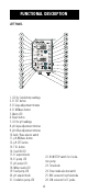
MECHANICAL LAYOUT
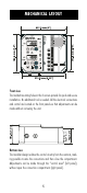
Front view
The molded mounting holes in the 4 corners provide for quick and secure
installation. No additional tool is needed. All the electrical connections
and control are located on the front panels so that adjustments can be
made without removing the unit.
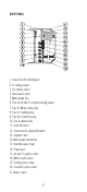
Bottom view
The modular design isolates the control circuitry from the contacts, mak-
ing possible to wire the connections and then close the compartment.
Adjustments can be made through the “control area” (left panel),
without open the connection compartment (right panel).