Instruction Manual HI 9912 Wall Mounted Dual pH/ORP Controller pH HI 99 1 pH 0 ALAR 2 M 100 ACID 3 OFFSET SLOPE ON 0.5 2 ALARM 1.5 0 SET mV OFF 0 2.5 2.0 pH 0 PROPOR TIONAL SECOND S SETTIN GS 200 5 7.5 ALAR M 90 1 MIN 10 UTES pH TIM ER ORP SET mV pH mV AL RDX FE 300 SET CAL ORP 100 ON 50 OFF mV PROP SET ALA 150 0 5 0 ORTIO NA SE L SE CONDS TTING S 50 RM 2.5 200 7.5 90 1 MIN ORP UTES TIM 10 LINE ER http://www.hannainst.
Dear Customer, Thank you for choosing a Hanna Product. Please read this instruction manual carefully before using the instrument. This manual will provide you with the necessary information for a correct use of the instrument, as well as a more precise idea of its versatility. If you need more technical information, do not hesitate to e-mail us at tech@hannainst.com. These instruments are in compliance with the directives. TABLE OF CONTENTS PRELIMINARY EXAMINATION ..........................................
PRELIMINARY EXAMINATION Remove the instrument from the packing material and examine it carefully to make sure that no damage has occurred during shipping. If there is any noticeable damage, notify your Dealer. Note: Save all packing materials until you are sure that the instrument functions correctly. Any defective item must be returned in the original packaging together with the supplied accessories. IMPORTANT: 1. Read the instructions before using the instrument. 2.
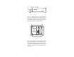
The Hanna controllers incorporate a triple contact alarm system. When activated, the alarm contacts will open or close, triggering the mechanism of your choice, whether a buzzer, light or any other electrical device. The controller is housed in a rugged, modular, fiber-reinforced ABS housing. All models can be wired to work with 110/115V or 220/240V 50/60 Hz power supplies. MECHANICAL LAYOUTS ELECTRODE WITH BNC CONNECTION MATCHING PIN FOR GROUND PROBE WIRING ACCESS PORTS Fig.
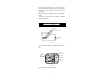
3“ 75 mm 25 mm 1“ 96.9 mm 3.8“ Fig. 3 Figure 3 is a dimensioned, bottom view of the Wall Mounted Controller. The modular design isolates the control circuitry from the contacts making it possible to make the connections and then close the compartment. Adjustments can then be made only in the control area, without having to open the contacts compartment. 6.9“ 174.8 mm 7.4“ 188.6 mm 227.8 mm 9“ 221.8 mm 8.7“ Fig. 4 Figure 4 is a dimensioned front view of the Wall Mounted Controller.
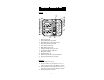
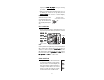
FUNCTIONAL DIAGRAM HI 9912 FRONT PANEL Left panel 13 14 2 3 4 5 6 7 8 9 2 4 1 15 pH pH SLOPE ON ALARM 0 1.5 5 10 MINUTES TIMER ALARM mV ALARM OXID mV FEED 700 SET pH ON 900 500 ALARM OFF 50 0 150 90 200 0 mV SECONDS PROPORTIONAL SETTINGS 20 200 mV 7.5 1 ORP CAL 19 0 SET 2.5 2.0 90 0 pH SECONDS PROPORTIONAL SETTINGS 0 2 ALARM 100 8 6 OFF 1 FEED 7 OFFSET 0.5 ALARM ACID pH 10 11 16 17 18 HI 9912 SET 21 SET ORP 5 2.5 7.
17. Triple contact alarm in a Normally Closed (NC) or a Normally Open (NO) position 18. Powered dosage terminals for pH correction 19. Powered dosage terminals for ORP correction 20. 110/115V or 220/240V power configuration 21. Incoming power terminals 22. Fuses BOTTOM VIEW 23 23. 24. 25. 26.
Specifications RANGE HI 9912 0.00 to 14.00 pH and 0 to 1000 mV 0.01 pH and 1mV RESOLUTION ACCURACY (@20°C/68°F) ±0.02 pH and ±5 mV TYPICAL EMC DEVIATION ±0.1 pH and ±6 mV CALIBRATION Through "OFFSET" and "SLOPE" trimmers for pH and “CAL” for ORP From 6 to 8 pH and 500 to 900 mV SETPOINT RANGE PROPORTIONAL CONTROL ALARM CONTACT DOSING TERMINALS POWER SUPPLY ENVIRONMENT WEIGHT ENCLOSURE CASE MATERIAL Two independent controls: pH from 0.0 to 2.
CONNECTIONS & WIRING GENERAL POINTS • The relay terminals of the controller are powered powered. You can simply hook up your pumps or electrovalves directly to the controller and do not need additional power supply. • Unscrew the 4 screws on the right hand panel and remove the cover and the gasket. Thread the wires through the access ports on the right hand side of the controller.
Diagram) and remove the jumpers shorting the matching pin terminals. • When using a separate probe for grounding purposes, wire it to the Matching Pin terminals on the right hand panel and remove the jumpers (see 14 and 15 - Functional Diagram). NOTE: REMOVE WHEN NEVER leave the jumper in when USING MATCHING PIN using an electrode with a matching pin. This can shorten the life of the electrode (reference) drastically.
• If the actual measurements are above or below the setpoints by a margin greater than the user-selectable alarm threshold, the alarm terminal is activated, triggering the mechanism of your choice. The alarm LED lights also come on. Due to the Consent feature feature, if the pH is in alarm, both the pH and ORP relays will be disactivated. However, if only ORP is in an alarm condition, only the ORP relay will be disactivated.
• For 110-115V, short the L and L1 terminals. Then wire the external power supply to the three terminals as shown. • Replace the cover with the gasket and screw it tight with the 4 screws provided. Only then connect the controller to the mains. NORMAL OPERATION & MEASUREMENT Make sure that the controller has been properly calibrated before commencing and that the pH and ORP setpoint(s) have been adjusted (see the following pages).
pH CALIBRATION 4 cm (1½") Make sure that the pH electrode and any ground probe have been properly connected and wired to the controller (see preceding pages) and that the meter is plugged to the mains. Calibration should be performed at a temperature similar to that of the liquid to be monitored. Use a Checktemp (or an accurate thermometer) as reference. Remove the electrode cap if it is still on the electrode.
SLOPE ADJUSTMENT: 4 cm (1½") • Rinse the electrode (and ground probe) thoroughly with water and immerse the bottom 4 cm (1.5”) in a pH 10.01 (HI 7010) or a pH 4.01 (HI HI 7010 7004) buffer solution. • Stir the electrode and wait for the display to stabilize before adjusting the "SLOPE" trimmer (see 5 - Functional Diagram) to display pH pH 10.01 (or 4.01) on the LCD if the temperature of the buffer solution is at 25°C (77°F).
ADJUSTEMENT OF SETPOINT(S) Make sure that the electrode (and any ground probe) is properly installed and calibrated (see the preceding pages). FOR pH pH Simply turn the pH ACID FEED dial (see 3 - Functional Diagram) and choose the desired value between 6 and 8 pH. ACID DOSING DIRECTION 6 ALARM FEED 7 8 SET The dosing terminals are activated when the pH value exceeds the setpoint. HI 9912 will then dose acidic solutions until the user-selected setpoint is reached.
to the difference between the measurement less the setpoint over the cycle. NOTE: • If the setting is left at 0 pH or 0 mV, the controller will operate as an ON/OFF control with no proportional dosage. In this case the controller will operate with a 0.1 pH or 7 mV hysteresis. 0 This causes the relay to chatter • Do not set the time cycle to 0. and can be detrimental to the controlling system and pump. e.g. pH proportional control Setpoint = 7.4 pH Measured value = 8.90 pH Delta = 8.90 - 7.40 = 1.
e.g. ORP proportional control Setpoint = 750 mV Measured value = 725 mV Delta = 750 - 725 = 25 mV Proportional settings = mV set to 100 and time cycle to 60 seconds The controller will be dosing 50 150 oxidants to increase redox to 0 90 200 0 the desired value. Since it is mV SECONDS PROPORTIONAL SETTINGS 25/100 = 25% away from the ideal setting, it will keep the dosing contacts activated for 25% of the time over the predetermined 60 seconds.
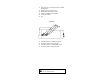
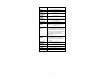
pH VALUES AT VARIOUS TEMPERATURES Please refer to the following chart for a more accurate pH calibration: TEMP °C °F 32 0 41 5 50 10 59 15 68 20 77 25 86 30 95 35 40 104 45 113 50 122 55 131 60 140 65 149 70 158 4.01 4.01 4.00 4.00 4.00 4.00 4.01 4.02 4.03 4.04 4.05 4.06 4.07 4.09 4.11 4.12 6.86 6.98 6.95 6.92 6.90 6.88 6.86 6.85 6.84 6.84 6.83 6.83 6.84 6.84 6.85 6.85 pH VALUES 7.01 9.18 9.46 7.13 9.39 7.10 9.33 7.07 9.27 7.04 9.22 7.03 9.18 7.01 9.14 7.00 9.10 6.99 9.07 6.98 9.04 6.98 9.01 6.98 6.98 8.
REDOX MEASUREMENT Redox measurements allow the quantification of the oxidizing or reducing power of a solution, and are commonly expressed in mV. Oxidation may be defined as the process during which a molecule (or an ion) loses electrons and reduction as the process by which electrons are gained. Oxidation is always coupled together with reduction so that as one element gets oxidized, the other is automatically reduced, therefore the term oxidation-reduction is frequently used.
The protective cap should also be filled with a few drops of HI 70300 storage solution if the electrode is not being used at all. Note: With industrial applications, it is always good practice to keep at least one spare electrode handy. When anomalies are not resolved with a simple maintenance, change the electrode to see if the problem is alleviated. ELECTRODE CONDITIONING & MAINTENANCE PREPARATION Remove the protective cap. DO NOT BE ALARMED IF ANY SALT DEPOSITS ARE PRESENT.
For more specific cleaning procedures, refer to the electrode’s instruction manual. IMPORTANT: After performing any of the cleaning procedures rinse the electrode thoroughly with distilled water and recalibrate the controller. TROUBLESHOOTING Evaluate your electrode performance based on the following. • Noise (Readings fluctuate up and down) could be due to clogged/dirty junction: Refer to the Cleaning Procedure above. • Dry Membrane/Junction: Soak in Storage Solution HI 70300 overnight.
This type of connection is very delicate and requires constant attention to maintain proper operating conditions. The conventional electrodes may be used for indoor applications but the cable length should not exceed 10 m (33'). MEDIUM DISTANCE, INDOOR/OUTDOOR INSTALLATION When an outdoor installation is required, it is normally necessary to install a transmitter to obtain accurate readings at distances from 10 to 50 m (33-165').
specific handbooks for process instrumentation, or simply call the Hanna office nearest to you for a complete list. pH CALIBRATION SOLUTIONS HI 7004L HI 7007L HI 7010L pH 4.01 buffer solution, 460 mL pH 7.01 buffer solution, 460 mL pH 10.
WARRANTY All Hanna controllers are warranted for two years against defects in workmanship and materials when used for their intended purpose and maintained according to instructions. Damages due to accident, misuse, tampering or lack of prescribed maintenance are not covered. This warranty is limited to free of charge repair or replacement of the meter only, if any malfunctioning is due to manufacturing defects. If service is required, contact the dealer from whom you purchased the instrument.
OTHER PRODUCTS FROM HANNA • • • • • • • • • • • • • • • • • • • • • CABLES AND CONNECTORS CALIBRATION AND MAINTENANCE SOLUTIONS CHEMICAL TEST KITS CHLORINE METERS CONDUCTIVITY/TDS METERS DISSOLVED OXYGEN METERS HYGROMETERS ION SPECIFIC METERS (Colorimeters) MAGNETIC STIRRERS Na/NaCl METERS pH/ORP/Na ELECTRODES pH METERS PROBES (DO, µS/cm, RH, T, TDS) PUMPS REAGENTS SOFTWARE THERMOMETERS TITRATORS TRANSMITTERS TURBIDITY METERS Wide Range of ACCESSORIES Most Hanna meters are available in the following forma
CE DECLARATION OF CONFORMITY DECLARATION OF CONFORMITY We Hanna Instruments Srl V.le delle industrie 12 35010 Ronchi di Villafranca (PD) ITALY herewith certify that the wall-mounted instrument: HI 9912 has been tested and found to be in compliance with the following regulations: IEC 801-2 IEC 801-3 IEC 801-4 EN 55022 EN 61010-1 Electrostatic Discharge RF Radiated Fast Transient Radiated, Class B User Safety Requirement Date of Issue: 07-06-1999 D.
HANNA LITERATURE Hanna publishes a wide range of catalogs and handbooks for an equally wide range of applications. The reference literature currently covers areas such as: • Water Treatment • Process • Swimming Pools • Agriculture • Food • Laboratory • Thermometry and many others. New reference material is constantly being added to the library. MAN9912R1 06/01 For these and other catalogs, handbooks and leaflets, contact your dealer or the Hanna Customer Service Center nearest to you.