Instruction Manual HI 9910 - HI 9911 HI 9920 Wall Mounted pH & ORP Controllers H I 99 pH pH ALAR M 1 0 2 TEMP. COM MTC P. ATC 4/20 mA OUT 0/20 PUT ACID SET OFFS ET CO ARSE FINE ON 0 SET ACID READ 60 -10 ALAR M SLOPE ALKALI NE SE T ALARM OFF 20 30 40 50 10 70 80 ACID FEED ALK 2.5 5 1.5 ACID ALK 7.5 0.5 SET ALK MTC °C 1 45 SET ALK 1 10 0 2.5 pH 2.0 0 PROP ORTIO SE NAL SE CONDS 90 TTING S 5 ACID 7.5 1 MINUT ES TIMER 10 LINE http://www.hannainst.
Dear Customer, Thank you for choosing a Hanna Product. Please read this instruction manual carefully before using the instrument. This manual will provide you with the necessary information for a correct use of the instrument, as well as a more precise idea of its versatility. If you need more technical information, do not hesitate to e-mail us at tech@hannainst.com. These instruments are in compliance with the directives EN 50081-1, 50082-1 and 61010-1. TABLE OF CONTENTS PRELIMINARY EXAMINATION ..........
PRELIMINARY EXAMINATION Remove the instrument from the packing material and examine it carefully to make sure that no damage has occurred during shipping. If there is any noticeable damage, notify your Dealer. Note: Save all packing materials until you are sure that the instrument functions correctly. Any defective item must be returned in the original packaging together with the supplied accessories. IMPORTANT: 1. Read the instructions before using the instrument. 2.
All models can be wired to work with 110/115V or 220/240V 50/60 Hz power supplies.
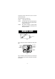
3“ 75 mm 25 mm 1“ 96.9 mm 3.8“ Fig. 3 Figure 3 is a dimensioned, bottom view of the wall mounted controllers. The modular design isolates the control circuitry from the contacts making it possible to make the connections and then close the compartment. Adjustments can then be made only in the control area, without having to open the contacts compartment. 6.9“ 174.8 mm 7.4“ 188.6 mm 227.8 mm 9“ 221.8 mm 8.7“ Fig. 4 Figure 4 is a dimensioned front view of the wall mounted controllers.
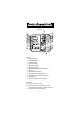
FUNCTIONAL DIAGRAM HI 9910 SINGLE SETPOINT, p H CONTROLLER FRONT PANEL 13 14 1 2 3 4 5 6 7 8 9 15 1 pH 0 OFFSET FINE COARSE 19 4/20 0/20 mA OUTPUT 20 SLOPE ALARM ON ACID SET OFF ALK READ SET pH ALARM 20 10 30 40 50 60 70 0 -10 80 0 DOSING 21 MTC °C 45 1 0.5 12 2 TEMP. COMP. MTC ATC SET POINT 10 11 16 17 18 pH ALARM HI 9910 5 2.5 1.5 0 2.0 pH SECONDS PROPORTIONAL SETTINGS 90 7.5 10 1 MINUTES ALARM DOSING TIME 22 LINE 23 Left panel 1. Liquid Crystal Display 2.
16. 17. 18. 19. 20. 21. 22. 23. Recorder output contacts Automatic or Manual Temperature Compensation switch 0 to 20 or 4 to 20 mA isolated output switch Triple contact alarm in a Normally Closed (NC) or a Normally Open (NO) position. Powered dosage terminals (Relay) 110/115V or 220/240V power configuration Incoming power terminals Fuses BOTTOM VIEW 24 25 24. Female BNC socket for combination pH electrode 25.
Specifications HI 9910 RANGE 0.00 to 14.00 pH RESOLUTION ACCURACY (@20°C/68°F) 0.01 pH ±0.02 pH TYPICAL EMC DEVIATION ±0.1 pH mA OUTPUT User-selectable 0 to 20 mA or 4 to 20 mA over the 0-14 pH range with isolated output Through "OFFSET" and "SLOPE" trimmers (Max. ±1.5 pH for offset and 80% to 110% for slope) Manual from -10 to 80 °C (14 to 176 °F) or automatic with a 3-wire Pt 100 probe from 0 to 50 °C (32 to 122 °F) From 0.00 to 14.
FUNCTIONAL DIAGRAM HI 9911 DUAL SETPOINT, pH CONTROLLER FRONT PANEL 13 14 1 2 3 4 5 6 7 8 9 15 HI 9911 16 17 18 pH ALARM 1 pH 0 2 TEMP. COMP. MTC ATC OFFSET COARSE 19 4/20 0/20 mA OUTPUT ACID SET FINE 20 SLOPE ALARM ALKALINE SET ON 10 ACID FEED OFF 40 50 30 70 -10 80 0 5 ALK 7.5 5 ACID 2.5 MTC °C 2.5 1.5 2.0 0 pH SECONDS PROPORTIONAL SETTINGS 90 1 SET ALK 21 10 1 45 1 SET ACID ALK READ ALK 60 0 0.5 12 ACID ALARM 20 10 11 SET 7.
18. 0 to 20 or 4 to 20 mA isolated output switch 19. Triple contact alarm in a Normally Closed (NC) or a Normally Open (NO) position. 20. Powered dosage terminals (Relays) 21. 110/115V or 220/240V power configuration 22. Incoming power terminals 23. Fuses BOTTOM CONNECTION 24 25 24. Female BNC socket for combination pH electrode 25. 4-mm Banana socket for ground probe Unplug the instrument from the power supply before wiring and replacing the fuses.
Specifications HI 9911 RANGE 0.00 to 14.00 pH RESOLUTION ACCURACY (@20°C/68°F) 0.01 pH ±0.02 pH TYPICAL EMC DEVIATION ±0.1 pH mA OUTPUT User-selectable 0 to 20 mA or 4 to 20 mA over the 0-14 pH range with isolated output Through "OFFSET" and "SLOPE" trimmers (Max. ±1.5 pH for offset and 80% to 110% for slope) Manual from -10 to 80 °C (14 to 176 °F) or automatic with 3-wire Pt 100 probe from 0 to 50 °C (32 to 122 °F) CALIBRATION TEMPERATURE COMPENSATION SETPOINT RANGE PROPORTIONAL CONTROL From 0.
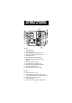
FUNCTIONAL DIAGRAM HI 9920 ORP CONTROLLER FRONT PANEL 13 14 1 3 4 5 6 7 8 9 HI 9920 16 mV ALARM 100 ORP mV 18 0 SET POINT CAL COARSE 200 19 mA OUTPUT 4/20 0/20 20 FINE ALARM ON OXID SET OFF RED READ SET mV DOSING ALARM 21 11 100 50 12 0 5 45 150 200 0 mV SECONDS PROPORTIONAL SETTINGS 2.5 90 7.5 22 10 1 MINUTES TIMER LINE 23 Left panel 1. Liquid Crystal Display 3. Fine setpoint trimmer 4. Coarse setpoint trimmer 5. Calibration trimmer 6. Dosing LED visual signal 7.
20. 21. 22. 23. Powered dosage terminals (Relay) 110/115V or 220/240V power configuration Incoming power terminals Fuses BOTTOM CONNECTION 24 25 24. Female BNC socket for combination ORP electrode 25. 4-mm Banana socket for ground probe Unplug the instrument from the power supply before wiring and replacing the fuses.
Specifications HI 9920 RANGE -500 to 1500 mV RESOLUTION 1 mV ACCURACY (@20°C/68°F) TYPICAL EMC DEVIATION mA OUTPUT CALIBRATION SETPOINT RANGE PROPORTIONAL CONTROL ±5mV ±6 mV User-selectable 0 to 20 mA or 4 to 20 mA over the -500 to 1500 mV range with isolated output Through "CAL" trimmer From -500 to 1500 mV with "COARSE" and "FINE" 2 trimmers with "OXID" or "RED" selection for oxidizing or reducing dosage ORP setting is adjustable from 0 to 200 mV and time cycle from 0 to 90 seconds ALARM CONTACT
• Before connecting the controller to the mains, wire the controller completely and make all the connections for pumps, alarm, electrode, set the alarm threshold and adjust the settings. Upon completion, replace the cover cover. Only then connect the controller to the power supply.
RELAY CONNECTIONS • Wire the external device or devices (pumps or electrovalves) directly to the relay terminal strip of the controller (see 20 Functional Diagram). The terminals are powered and hence you do not need an external power supply for the pump or electrovalve. There is one terminal strip for HI 9910 and HI 9920 and two for HI 9911. BL DOSING PUMP HI 9910 pH ALARM 1 pH 0 2 TEMP. COMP.
ON • The alarm ON/OFF switch is only to disable the alarm terminal (e.g. the buzzer will ALARM OFF not sound). However, all other functions such as disactivation of the dosing relay remain unvaried, i.e. the pump ceases to dose until the alarm condition is alleviated. • The controllers provide for automatic fail-safe security by activating the alarm if there is a power failure, regardless of whether the NC or NO configurations were chosen.
TEMPERATURE COMPENSATION (HI 9910 and HI 9911 only) • Manual Temperature Compensation: Move the selector to the MTC position (see 17-Functional Diagram). Then manually set the temperature by turning the dial (see 10 - Functional Diagram) to the correct working temperature. MTC ATC Temp. compensation selector 20 10 30 40 50 60 0 70 -10 80 MTC °C • Automatic Temperature Compensation: Move the selector to the ATC position (see 17-Functional Diagram).
NORMAL OPERATION and MEASUREMENT Make sure that the controller has been properly calibrated before commencing and that the pH or ORP setpoint(s) have been adjusted (see the following pages). The pH or ORP electrodes and any ground probes must be properly connected and wired to the controller (see preceding pages). Remove the protecteive cap if it is still on the tip of the electrode. SET Ensure that the electrode is properly installed and lies permanently in the solution to a depth of at least 4cm/1.5”.
pH CALIBRATION (HI 9910 and HI 9911) 4 cm (1½") Make sure that the pH electrode and any ground probe have been properly connected and wired to the controller (see preceding pages) and that the meter is plugged to the mains. Calibration should be ideally performed at a temperature similar to that of the liquid to be monitored. Use a Checktemp (or an accurate thermometer) as reference for temperature compensation. Remove the electrode cap if it is still on the electrode.
as that on the Checktemp and make sure the selector is in the MTC position (see 17 - Functional Diagram). • Wait for the measurement to stabilize and then adjust the "OFFSET" trimmer to display pH 7.01 on the LCD if the tempera- pH ture of the buffer solution is at 25°C (77°F). 7.
ORP CALIBRATION (HI 9920) 4 cm (1½") Make sure that the ORP electrode and any ground probe have been properly connected and wired to the controller (see preceding pages) and that the meter is plugged to the mains. Remove the electrode cap if it is still on the electrode. During calibration, introduce both the electrode and the ground probe (if in use) to the known solution. An immersion level of 4 cm (1.5”) is recommended.
ADJUSTEMENT OF SETPOINT(S) Make sure that the electrode (and any ground probe) is properly installed and calibrated (see the preceding pages). FOR HI 9910 Turn the switch to the "SET" position (see 7 - Functional Diagram). The display will show the previously adjusted value (e.g. pH 8.00). SET 8.
e.g. Dosing base liquids Set point = pH 6.00 Measured value = pH 4.00 To adjust the sample stream to the setpoint, you need to dose base, therefore select "ALK". ACID ALK FOR HI 9911 (DUAL-POINT ADJUSTMENT) a) ACID SETPOINT and DOSAGE Turn the switches to "SET" and “ACID” (see 7 and 8 - Functional Diagram) to set the upper limit and to direct the controller to lower the pH. The display will show the higher setpoint (e.g. pH 7.00). ACID SET 7.
Using a small screwdriver, adjust the “ALKALINE SET” trimmers. First adjust the “COARSE” trimmer and then fine tune with the “FINE” 5.18 pH pH 5.00 ACID SET OFFSET COARSE ACID SET FINE SLOPE OFFSET COARSE ALKALINE SET FINE SLOPE ALKALINE SET trimmer (see 3 and 4 - Functional Diagram) until the desired set value is displayed (e.g. pH 5.00). NOTE: • The “FINE” trimmer can adjust up to ±1.5 pH.
DOSING DIRECTION Select the direction of dosing through the "OXID"/”RED” switch (see 8 - Functional Diagram). For reducing dosage (i.e. lowering the mV value) leave the selector on "RED". Likewise, for oxidizing solutions (to increase the mV) select the “OXID” position. e.g. Dosing reducing substances Setpoint = mV 650 Measured value = mV 700 switch to the "RED" position (see 8 - Functional Diagram). OXID RED e.g.
e.g. pH proportional control Setpoint = pH 5.00 Measured value = 6.50 Delta = 6.5 - 5.0 = 1.5 pH Proportional settings: pH set to 2 and time cycle to 60 seconds. 45 1 0.5 0 1.5 2.0 0 pH SECONDS PROPORTIONAL SETTINGS 90 The controller will be dosing acids to reduce pH to the desired limit. Since it is 1.50/2.00 = 75% away from the ideal setting, it will keep the dosing terminals activated for 75% of the time over the predetermined 60 seconds.
.g. ORP proportional control Setpoint = 725 mV Measured value = 700 mV Delta = 725 - 700 = 25 mV Proportional settings = mV set to 100 and time cycle to 60 seconds. 100 50 0 45 150 200 0 mV SECONDS PROPORTIONAL SETTINGS 90 The controller will be dosing reductants to reduce redox to the desired value. Since it is 25/100 = 25% away from the ideal setting, it will keep the dosing relay activated for 25% of the time over the predetermined 60 seconds.
OVERDOSAGE TIMER All models provide for an overdosage alarm 5 system ranging from 1 to 10 minutes . The 2.5 7.5 operator can set the maximum amount of time that the dosage terminals should con10 1 tinuously remain activated. Should this period ALARMMINUTES DOSING TIME elapse, the alarm terminals are activated (and dosage disactivated to ensure that chemicals have not run out or pumps or electrovalves have not ceased to function properly).
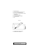
pH VALUES AT VARIOUS TEMPERATURES Please refer to the following chart for a more accurate pH calibration: TEMP °C °F 0 32 5 41 10 50 15 59 20 68 25 77 30 86 35 95 40 104 45 113 50 122 55 131 60 140 65 149 70 158 4.01 4.01 4.00 4.00 4.00 4.00 4.01 4.02 4.03 4.04 4.05 4.06 4.07 4.09 4.11 4.12 6.86 6.98 6.95 6.92 6.90 6.88 6.86 6.85 6.84 6.84 6.83 6.83 6.84 6.84 6.85 6.85 pH VALUES 7.01 9.18 9.46 7.13 9.39 7.10 9.33 7.07 9.27 7.04 7.03 9.22 9.18 7.01 9.14 7.00 9.10 6.99 9.07 6.98 9.04 6.98 9.01 6.98 8.99 6.
REDOX MEASUREMENT (HI 9920) Redox measurements allow the quantification of the oxidizing or reducing power of a solution, and are commonly expressed in mV. Oxidation may be defined as the process during which a molecule (or an ion) loses electrons and reduction as the process by which electrons are gained. Oxidation is always coupled together with reduction so that as one element gets oxidized, the other is automatically reduced, therefore the term oxidation-reduction is frequently used.
between 200 and 250 mV. When not in use, the electrode tip should be kept moist in order for the reference junction, especially Teflon models, to respond quickly. Otherwise, soak the electrode overnight in a HI 70300 storage solution or allow more time upon installation for its stabilization. Also keep the electrode far from any type of mechanical stress which might cause damage. Install the electrode in such a way that it is constantly in a well filled with the sample (stream or tank) and does not dry up.
ELECTRODE CONDITIONING & MAINTENANCE PREPARATION Remove the protective cap. DO NOT BE ALARMED IF ANY SALT DEPOSITS ARE PRESENT. This is normal with electrodes and they will disappear when rinsed with water. During transport tiny bubbles of air may have formed inside the glass bulb (membrane). Shake down the electrode as you would do with a glass thermometer to remove these bubbles. If the bulb and/or junction are dry, soak the electrode in a HI 70300 Storage Solution overnight.
TROUBLESHOOTING Evaluate your electrode performance based on the following. • Noise (Readings fluctuate up and down) could be due to a clogged/dirty junction: Refer to the Cleaning Procedure above. • Dry Membrane/Junction: Soak in Storage Solution HI 70300 overnight. Check to make sure the installation is such as to create a well for the electrode bulb to constantly remain moist. • Low Slope: Refer to the cleaning procedure above.
MEDIUM DISTANCE, INDOOR/OUTDOOR INSTALLATION When an outdoor installation is required, it is normally necessary to install a transmitter to obtain accurate readings at distances from 10 to 50 m (33-165'). Since the introduction of AmpHel electrodes these distances are no longer a problem. You can now connect your meter directly to an AmpHel electrode, saving the cost of a transmitter. The standard cable length of the AmpHel electrode is 5 m (16.5').
pH CALIBRATION SOLUTIONS HI 7004L HI 7007L HI 7010L pH 4.01 buffer solution, 460 mL pH 7.01 buffer solution, 460 mL pH 10.
WARRANTY All Hanna controllers are warranted for two years against defects in workmanship and materials when used for their intended purpose and maintained according to instructions. Damages due to accident, misuse, tampering or lack of prescribed maintenance are not covered. This warranty is limited to free of charge repair or replacement of the meter only, if any malfunctioning is due to manufacturing defects. If service is required, contact the dealer from whom you purchased the instrument.
OTHER PRODUCTS FROM HANNA • • • • • • • • • • • • • • • • • • • • • CABLES AND CONNECTORS CALIBRATION AND MAINTENANCE SOLUTIONS CHEMICAL TEST KITS CHLORINE METERS CONDUCTIVITY/TDS METERS DISSOLVED OXYGEN METERS HYGROMETERS ION SPECIFIC METERS (Colorimeters) MAGNETIC STIRRERS Na/NaCl METERS pH/ORP/Na ELECTRODES pH METERS PROBES (DO, µS/cm, RH, T, TDS) PUMPS REAGENTS SOFTWARE THERMOMETERS TITRATORS TRANSMITTERS TURBIDITY METERS Wide Range of ACCESSORIES Most Hanna meters are available in the following forma
CE DECLARATION OF CONFORMITY DECLARATION OF CONFORMITY We Hanna Instruments Srl V.le delle industrie 12 35010 Ronchi di Villafranca (PD) ITALY herewith certify that the wall-mounted instruments: HI 9910 HI 9911 HI 9920 have been tested and found to be in compliance with the following regulations: IEC 801-2 IEC 801-3 IEC 801-4 EN 55022 EN 61010-1 Electrostatic Discharge RF Radiated Fast Transient Radiated, Class B User Safety Requirement Date of Issue: 07-06-1999 D.
HANNA LITERATURE Hanna publishes a wide range of catalogs and handbooks for an equally wide range of applications. The reference literature currently covers areas such as: • Water Treatment • Process • Swimming Pools • Agriculture • Food • Laboratory • Thermometry For these and other catalogs, handbooks and leaflets, contact your dealer or the Hanna Customer Service Center nearest to you. To find the Hanna Office in your vicinity, check our home page at www.hannainst.com. h t t p : / / w w w .