
User Guide

OPERATIONAL GUIDEOPERATIONAL GUIDE
OPERATIONAL GUIDEOPERATIONAL GUIDE
OPERATIONAL GUIDE
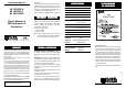
POWER CONNECTION
HI 983315-0 and HI 98331500HI 983315-0 and HI 98331500
HI 983315-0 and HI 98331500HI 983315-0 and HI 98331500
HI 983315-0 and HI 98331500
Connect a 2-wire power cable to the terminal strip while
paying attention to the correct positive and negative polari-
ties (12 VDC).
HI 983315-1HI 983315-1
HI 983315-1HI 983315-1
HI 983315-1
Connect a 3-wire power cable to the terminal strip while
paying attention to the correct earth, neutral and line
contacts (115/230 VAC).
ALARM CONTACT
Use this contact (maximum 5A, 240VAC, 30VDC) for connec-
tion to an alarm or dosing system. The unit acts as a switch
to control an external device.
Notes:Notes:
Notes:Notes:
Notes:
• All external cables connected to the rear panel should
end with wire lugs.
• It is recommended to cover the unused terminals with
insulating tape.
• At start up the meter needs a few seconds to stabilize.
Wait until a stable reading is displayed.
ACCESSORIESACCESSORIES
ACCESSORIESACCESSORIES
ACCESSORIES
HI 7634-00 EC/TDS probe
HI 70033P 84 µS/cm Calibration solution, 20mL
HI 7033M 84 µS/cm Calibration solution, 230mL
HI 7033L 84 µS/cm Calibration solution, 460mL
HI 7061M Electrode cleaning solution, 230 mL
HI 710005 12 VDC power adapter, US plug
HI 710006 12 VDC power adapter, European plug
HI 710012 12 VDC power adapter, Australian plug
HI 710013 12 VDC power adapter, South African plug
HI 710014 12 VDC power adapter, UK plug
HI 731326 Calibration Screwdriver (20 pcs)
CALIBRATION
Make sure the meter is in the measurement mode (the
“MEAS” LED lights on).
Immerse the probe in HI 7033 (84 µS/cm) calibration
solution.
Shake briefly and wait for reading to stabilize.
Using a small screwdriver adjust the calibration trimmer
until the meter displays “42” ppm.
SETPOINT
Press the “SET” key. The display will show the default or
previously adjusted value for the setpoint.
Using a small screwdriver, adjust the “SET” trimmer until
the required limit value is displayed.
PROBE MAINTENANCE
To improve probe performance and prolong its life, it is
recommended to clean it regularly.
• Immerse the tip of the probe in HI 7061 Cleaning
Solution at least for one hour.
• If a more thorough cleaning is required, brush the
metal pins with very fine sandpaper.
• After cleaning, rinse the probe with tap water and
recalibrate the meter.
• When not in use, clean the probe before storing it.
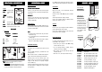
Front view of the
panel-mounted unit
Side view of the
panel-mounted unit
Adjustable location brack-
ets (supplied with the
meter) allow the controller
to slide into the cutout and
will hold the unit securely
in place. 95 mm (3.74") is
the minimum amount of
space required to install
the controller.
Panel-mounted
unit assembling
view
73mm
2.87"
79mm
3.11"
42mm
1.65"
49mm
1.93"
95mm MIN
3.74"
76mm
3"
0.25/4mm
0.01/0.160"
79mm
3.11"
ADJUSTABLE
LOCATION
BRACKET
HI983315 LAYOUTHI983315 LAYOUT
HI983315 LAYOUTHI983315 LAYOUT
HI983315 LAYOUT
HI 740146
FUNCTIONAL DESCRIPTIONFUNCTIONAL DESCRIPTION
FUNCTIONAL DESCRIPTIONFUNCTIONAL DESCRIPTION
FUNCTIONAL DESCRIPTION
FRONT PANELFRONT PANEL
FRONT PANELFRONT PANEL
FRONT PANEL
Keypad
SETSET
SETSET
SET To display setpoint
MEASMEAS
MEASMEAS
MEAS To display measure-
ment
Trimmers
CALCAL
CALCAL
CAL For calibration
SETSET
SETSET
SET To adjust setpoint
LEDs
SETSET
SETSET
SET ON when the LCD
displays set value
MEASMEAS
MEASMEAS
MEAS ON when the LCD displays measured value
ALARMALARM
ALARMALARM
ALARM ON when the alarm contact is closed
REAR PANELREAR PANEL
REAR PANELREAR PANEL
REAR PANEL
1. Power Supply:
HI 983315-0 HI 983315-0
HI 983315-0 HI 983315-0
HI 983315-0
HI 983315-1 HI 983315-1
HI 983315-1 HI 983315-1
HI 983315-1
HI 98331500 HI 98331500
HI 98331500 HI 98331500
HI 98331500
12 VDC 115/230 VAC 12 VDC 115/230 VAC
12 VDC 115/230 VAC 12 VDC 115/230 VAC
12 VDC 115/230 VAC
L1:L1:
L1:L1:
L1: Positive 230 VAC
L2:L2:
L2:L2:
L2: Negative 115 VAC
L3:L3:
L3:L3:
L3: --- Neutral
L4:L4:
L4:L4:
L4: --- Protection Earth
NoteNote
NoteNote
Note
: :
: :
: the power input is internally protected by a 400 mA fuse
2.
Alarm Contact: A1, A2.
3.
Probe Connection: follow the above diagram and connect the
colored wires of probe cable as indicated. It is recommended
to connect the shield (P5) to avoid any interference.
OPERATING THE METER
All operations can be controlled via front panel keys and
trimmers.
“SET” and “MEAS” LEDs light up to indicate which is the
operating function.
Make sure that the meter is calibrated and the Setpoint is
properly selected before performing any measurement.
Attach the probe to the meter. Install the probe in the
fittings or immerse it in the solution to be monitored, while
making sure that metal pins are completely submerged.
Press the “MEAS” key.
The LCD will show the TDS value of the solution in ppm unit.
Any initial variation on readings may be due to tempera-
ture compensation.
The “ALARM” LED will light up when the alarm contact is
closed, to indicate a TDS value higher than selected setpoint.