Instruction Manual HI 98188 USP Compliant EC, TDS, NaCl, Resistivity, Temperature Meter HI 98188 EC/TDS/NaCl/Resistivity Meter w w w. h a n n a i n s t .
Dear Customer, Thank you for choosing a Hanna Instruments product. Please read this instruction manual carefully before using the instruments. This manual will provide you with the necessary information for correct use of the instruments, as well as a precise idea of their versatility. If you need additional technical information, do not hesitate to e-mail us at tech@hannainst.com or turn to the back cover for our worldwide contact list. directives.
PRELIMINARY EXAMINATION Remove the instrument from the packing material and examine it carefully to make sure that no damage has occurred during shipping. If there is any damage, notify your Dealer or the nearest Hanna Customer Service Center. Each instrument is supplied with: • HI 76313 4-ring probe with temperature sensor (4m cable) • 100 mL Plastic Beaker • 4 x 1.
GENERAL DESCRIPTION The HI 98188 instrument is state-of-the-art, heavy-duty conductivity meter, designed to provide laboratory results and accuracy under harsh industrial conditions. The USP standard compliance makes the instrument useful for pure water determination. It is provided with a series of new diagnostic features which add an entirely new dimension to the measurement of conductivity, by allowing the user to dramatically improve the reliability of the measurement: • 7 memorized standards (0.
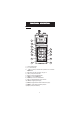
FUNCTIONAL DESCRIPTION Front view 1 2 HI 98188 EC/TDS/NaCl/Resistivity Meter 3 13 4 5 6 7 ESC HELP CAL RANGE SETUP RCL MODE ON OFF GLP LIGHT 8 12 11 10 9 1) Liquid Crystal Display (LCD). 2) F1, F2, F3 functional keys. / keys to manually increase/decrease the parameters or to scroll between 3) the parameter list. 4) ESC to leave current mode, exit calibration, setup, help. etc. 5) CAL key, to enter/exit calibration mode. 6) RCL key, to enter/exit view logged data mode.
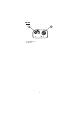
Top view 14) Electrode DIN connector. 15) USB connector.
SPECIFICATIONS 0 to 400 mS/cm (shows va lues up to 1000 mS/cm) Actua l cond uctivity 1000 mS/cm 0.001 to 9.999 µ S/cm* 10.00 to 99.99 µ S/cm 100.0 to 999.9 µ S/cm 1.000 to 9.999 mS/cm 10.00 to 99.99 mS/cm 100.0 to 1000.0 mS/cm (a utora ng ing ) Ra ng e EC Resolution 0.001 µ S/cm* 0.01 µ S/cm 0.01 µ S/cm 0.001 mS/cm 0.01 mS/cm 0.1 mS/cm Accura cy ±1% of rea d ing (±0.01 µ S/cm or 1 d ig it wichever g rea ter) 1.0 to 99.9 ohms 100 to 999 ohms 1.00 to 9.99 Kohms 10.0 to 99.9 Kohms 100 to 999 Kohms 1.
Salinity Temperature E C Calibration Range % NaCl 0.0 to 400.0 % Sea water scale: 0.00 to 80.00 (ppt) Practical salinity: 0.01 to 42.00 (PSU) Resolution 0.1 % 0.01 Accuracy ±1% of reading Range -20.0 to 120.0 °C Resolution 0.1 °C Accuracy ±0.2 °C (excluding probe error) Automatic up to 5 points with 7 memorized standards (0.00 µ S/cm, 84.0 µ S/cm, 1.413 mS/cm, 5.00 mS/cm, 12.88 mS/cm, 80.0 mS/cm, 111.8 mS/cm) Cell constant setup NaCl Calibration 0.010 to 10.000 Max.
OPERATIONAL GUIDE INITIAL PREPARATION The instrument is supplied complete with rechargeable batteries. Proceed with a complete charging process before starting (see page 63). To prepare the instrument for field measurements close the serial communication socket with proper stopper (to ensure waterproof protection). Connect the EC probe to the DIN connector on the top of the instrument. Tighten the thread ring. Make sure the probe sleeve is properly inserted. Turn the instrument ON by pressing ON/OFF key.
EC range The conductivity range is from 0 to 400 mS/cm . The actual conductivity range (the uncompensated conductivity) is up to 1000 mS/cm. The instrument will display conductivity readings up to 1000 mS. Note: The symbol in front of the temperature reading means that the temperature can be entered by the user (Manual option selected in Setup, or temperature out of range). Resistivity range The reciprocal of the conductivity of a material is the resistivity.
From practical reasons, the salinity of a solution is derived from the salinity of the seawater.
According to the definition, salinity of a sample in psu (practical salinity units) is calculated using the following formula: RT - coefficient; CT(sample) - uncompensated conductivity at T °C; C(35,15)= 42.914 mS/cm - the corresponding conductivity of KCl solution containing a mass of 32.4356 g KCl / 1 Kg solution; rT - temperature compensation polynom a0 = 0.008 b0=0.0005 a1 = -0.1692 b1= -0.0056 a2 = 25.3851 b2= -0.0066 a3 = 14.0941 b3= -0.0375 a4 = -7.0261 b4= 0.0636 a5 = 2.7081 b5= -0.0144 c0 = 0.
Notes: • If the meter displays the top of the range blinking, the reading is out of range. • If the stability indicator “ ” blinks, the reading is unstable. • Make sure the meter is calibrated before taking measurements. • If measurements are taken successively in different samples, for accurate readings it is recommended to rinse the probe thoroughly with deionized water before immersing it into the samples.
AUTORANGING The EC, Resistivity and TDS scales are autoranging. The meter automatically sets the scale with the highest possible resolution. By pressing Lock, the autoranging feature is disabled and the current range is frozen on the LCD. The “Range: Locked” message is displayed. To restore the autoranging option press “AutoRng” functional key again. The autoranging mode is also disabled by selecting a “fixed range” in the Setup menu.
TEMPERATURE COMPENSATION Two selectable temparature sources are available: reading directly from the sensor inside the probe or manual entry. Three options of compensating temperature are available: Linear Temperature Compensation: The conductivity of a solution with a specific electrolyte concentration changes with temperature. The relationship of the change in conductivity as a function of temperature is described by a solution’s temperature coefficient.
CONDUCTIVITY VERSUS TEMPERATURE CHART The conductivity of an aqueous solution is the measure of its ability to carry an electrical current by means of ionic motion. The conductivity invariably increases with increasing temperature. It is affected by the type and number of ions in the solution and by the viscosity of the solution itself. Both parameters are temperature dependent.
USP MEASUREMENT Pharmaceutical laboratories working in the US market are obliged to respect th the regulations set down by the US Pharmacopoeia. The 5 supplement of USP24-NF19 lays down the rules for checking the quality of pure or fully deionized water used for the production of injection products. The conductivity of water provides information on its chemical composition. It is therefore logical that makes this the main parameter to measure.
are trapped. Connect the probe to the meter enter USP mode and press the Stage 1 key. The instrument will perform a temperature and conductivity measurement (using a non-temperature corrected conductivity reading). • Using the Stage 1 temperature and conductivity requirement table the corresponding conductivity limit at that temperature is determined. • If the measured conductivity is no greater than the table value the water meets the requirements of the test for conductivity.
Stage 2 Determine the influence of CO2 Note: Stability criteria <0.5 %/min corresponds in fact to a change in conductivity <0.02 mS/cm per minute (equivalent to 0.1 mS/cm per 5 minutes), as required in the Stage 2 USP document. • Transfer a sufficient amount of water (100 mL or more) to a thermostatic vessel, and stir the test specimen. Adjust the temperature and maintain it at 25 ±1 ºC. We recommend using a thermostatic bath. • Rinse the cell carefully with deionized water.
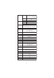
Stage 3 pH and conductivity requirements (For atmosphere and temperature equilibrated samples only) pH Conduct ivit y µS/cm 5.0 4.7 5.1 4.1 5.2 3.6 5.3 3.3 5.4 3.0 5.5 2.8 5.6 2.6 5.7 2.5 5.8 2.4 5.9 2.4 6.0 2.4 6.1 2.4 6.2 2.5 6.3 2.4 6.4 2.3 6.5 2.2 6.6 2.1 6.7 2.6 6.8 3.1 6.9 3.8 7.0 4.
USP MODE PROCEDURES Press Mode key while in EC range to enter USP mode. The instrument will display the USP main screen. Press Stage 1 to start with first stage evaluation. Press Stage 2 to start with second stage evaluation. If Stage 1 is pressed a tutorial screen is displayed. Use the Arrow keys to scroll the tutorial message. Press Continue to skip the tutorial message and enter EC measuring mode. If the temperature source is manual entry, press USP Fact.
Press Log to memorise USP Stage 1 report. The record number and the amount of free log space in % is displayed for few seconds. Note: If the log space is full enter view logged data mode by pressing RCL key and free log space by deleting previously memorized records. If the sample reading didn’t meet the USP stage 1 criteria, the “USP Not Met” message is displayed. Press ESC to return to the USP main screen. Press Report to view USP report. Press Log to memorise the Stage 1 report.
Wait until the reading is stable (about 5 minutes). Note: If the input record has an instability higher than 1mS, stability period will be reset. The completion time bar will remain empty. The “USP Met” message will be displayed if the USP stage 2 criteria is reached. Press Report to view the USP report. Press key to scroll the report screens. Press Log to memorise report. Notes:• The record number will be the same as at the Stage 1 report (informations of the same analyse).
Press Continue to enter USP Stage 3 analyze. The instrument will display the sample pH setting mode. Use a calibrated pH meter to read the pH value of the sample. Use ARROW keys to set the value to that red from the pH meter. Press Accept to confirm the pH setting. The USP Stage 3 report will be displayed. The report will include all stages information. Press key to scroll the report pages . Press Log to memorise the report. Press ESC to return to USP main screen.
USER CALIBRATION To enter User Calibration screen press CAL key while in EC or Salinity range. From EC range Press the corresponding functional key to enter: • EC user calibration. • Probe replatinization. • Temperature user calibration. From Salinity % range Press the corresponding functional key to enter: • Salinity % user calibration. • Temperature user calibration.
EC CALIBRATION It is recommended to calibrate the instrument frequently, especially if high accuracy is required. The EC range should be recalibrated: • Whenever the EC electrode is replaced. • At least once a week. • Before USP measurement. • After testing aggressive chemicals. • When calibration alarm time out is expired - “CAL DUE” blinks (if feature is enabled in SETUP).
• From EC range press CAL to enter calibration screen. • Leave the probe in the air and press EC. The instrument will display the measured EC on the LCD, first expected standard and the temperature reading. • If necessary, press the ARROW keys to select a different standard value. • The “ ” tag will blink on the LCD until the reading is stable. • When the reading is stable and close to the selected buffer, CFM functional key is displayed. • Press CFM to confirm first point.
functional key is displayed. • Press CFM to confirm calibration. • The calibrated value and the third expected standard value will be displayed. • After the second calibration point is confirmed, immerse the EC electrode into the third standard solution and stir gently. Tap the probe repeatedly to remove any air bubbles that may be trapped inside the sleeve. The instrument will automatically detect the standard value. • If necessary, press the ARROW keys to select a different standard value.
• Press CFM to confirm calibration. • The calibrated value and the fourth expected standard value will be displayed. • After the third calibration point is confirmed, immerse the EC electrode into the fourth standard solution and stir gently. Tap the probe repeatedly to remove any air bubbles that may be trapped inside the sleeve. • The instrument will automatically detect the standard value. • If necessary, press the ARROW keys to select a different standard value.
• After the fourth calibration point is confirmed, immerse the EC electrode into the fifth standard solution and stir gently. • If necessary, press the ARROW keys to select a different standard value. • The “ ” tag will blink on the LCD until the reading is stable. • When the reading is stable and close to the selected standard, the CFM functional key is displayed. • Press CFM to confirm calibration. • The instrument stores the calibration values and returns to normal measurement mode.
CLEAR CALIBRATION Press Clear functional key when displayed to clear old calibrations. All old calibrations, are cleared and the instrument continues calibration. The points confirmed in current calibration are kept. Note: If Clear calibration is invoked during the first calibration point, the instrument returns to measurement mode. REPLACE CALIBRATION STANDARD Each time a standard is confirmed the new calibration parameters replace the old calibration parameters of the corresponding standard.
• The instrument enters the Salinity calibration screen. • Press Salt. The measured % NaCl, the temperature and the 100% NaCl standard are displayed. • Rinse the probe with some of the calibration solution or deionized water. Immerse the probe into HI 7037L solution. Tap the probe repeatedly to remove any air bubbles that may be trapped inside the sleeve. • The “ ” tag will blink on the LCD until the reading is stable. • When the reading is stable, the CFM functional key is displayed.
GOOD LABORATORY PRACTICE (GLP) GLP is a set of functions that allows storage and retrieval of data regarding the maintenance and status of the electrode. All data regarding EC and NaCl calibration is stored for the user to review when necessary. EXPIRED CALIBRATION The instrument is provided with a real time clock (RTC), in order to monitor the time elapsed since the last EC/NaCl calibration.
The instrument will display a lot of data including calibration standards, offset, time and date, etc. Use the Arrow keys to select the offset or calibration standards, in order to view new information. To see more information press More. • More information regarding offset. • More information regarding standards. Notes: • Standards displayed in video inverse mode are from previous calibrations.
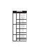
SETUP Setup mode allows viewing and modifying the measurement parameters. These are general SETUP parameters for all the ranges and range specific parameters. The following table lists the general SETUP parameters, their valid range and the factory default settings.
The following table lists the specific range parameters: Item Calibr. Timeout (EC, NaCl) Out cal range check (EC range only) Temperature source Temperature compensation mode Range select Description Valid value Number of days after Disable, 1 to 7 days Calibration warning is displayed Display warning if the Enable/Disable reading is too far from the calibration points Cell constant Manual set of the cell constant Set the coeficient 0.00 to 10.
GENERAL PARAMETER SCREENS Select Profile Focus on the Select Profile item. Press Select. The list with memorised profiles is displayed. Press Add to add a new profile to the list (max 10). Use the Arrow keys to focus on the desired profile. Press Select to select the profile and exit to Setup. Press View to view profile information.
Press Delete to delete selected profile. The Delete key is displayed only if more than one profile is in the list. Press Accept to confirm the deletion or Cancel to cancel and return to the previous screen. Press ESC to return to profile list screen. Logging interval Focus on the Logging interval item. Press Modify. Use the Arrow keys to select the logging interval. If “Disabled” option is selected the Autolog feature is disabled and Log on demand is enabled. Press Accept to confirm the value.
Contrast Focus on the Contrast item. Press Modify. Use / keys to change contrast then press Accept to confirm. Press ESC to leave without changing. Auto Light Off Focus on the Auto Light Off item. Press 5, 10 or 30 to change settings. Press one of the functional key to change the option. Auto Power Off Focus on the Auto Power Off item.
Press Modify. Press ARROW keys to select internal interval then press Accept. Press ESC to leave without changing. Date/Time Focus on the Date/Time item. Press Modify. Use / keys to select item. Use ARROW keys to change focused values. Press Accept to confirm new setting, or ESC to leave without changing. Time Format Focus on the Time Format item. Press functional key to change the option. Date Format Focus on the Date Format item.
Press Modify. Use ARROW keys to select date format then press Accept. Press ESC to leave without changing. Language Focus on the Language item. Use the desired functional key to change the option. Wait until new language is loaded. If any language can be loaded, the instrument will work in safe mode. In this mode all messages are displayed in English and Help is not available. Beep On Focus on Beep On item. Press the displayed functional key to enable/disable key.
Press Modify. Use ARROW keys to change the instrument ID. Press Accept to confirm or ESC to exit without saving. Baud Rate Focus on the Baud Rate item. Press Modify. Use ARROW keys to select the desired communication baud. Press Accept to confirm or ESC to exit. Meter information Focus on the Meter Information item. Press Select.
The meter informations are displayed: -firmware version -language version -mV and temperature factory calibration time/date -battery capacity RANGE SPECIFIC PARAMETERS Calibration Timeout Focus on the Calibration Timeout item. Press Modify. Use ARROW keys to set desired value. Press Accept to confirm or ESC to return without saving. Note: If enabled “CAL DUE” warning will be displayed, the set number of days after calibration is over passed.
Press the corresponding functional key in order to enable/disable this feature. If enabled, a warning message is displayed when the EC reading is too far from the EC calibration points. Temperature source Focus on the Temperature source item. Press the displayed functional key in order to change the option. Select Probe in order to take the temperature automatic with the temperature sensor inside the electrode. Select Manual in order to set the temperature using the ARROW keys.
Press Modify to select ranging mode. Use the Arrow keys to change selection. Press Accept to confirm or ESC to exit without saving. If Automatic is selected the instrument changes the range automatically according with the input. If one of the range is selected all the readings are displayed on the corresponding range. The readings will be displayed with maximum 6 digits. If the reading exceeds the maximum number of digits for the fixed range, the maximum value is displayed blinking.
Press the displayed functional key in order to change option. If enabled, the “Out Cal Range” message will be displayed if the EC reading is not within the calibration range. Temperature Coefficient Focus on the Temperature Coefficient item. Press Modify in order to set the temperature coefficient. Use the Arrow keys to change the value. Press Accept to confirm or ESC to exit without changing. Temperature Reference Focus on the Temperature Reference item.
L OG O N DEMAND DEMA ND This feature allows the user to log up to 400 readings. All logged data can be transferred to a PC through the USB port. LOGGING THE CURRENT DATA To store the current reading into memory, press LOG while in measurement mode. The instrument will display for few seconds the record number and the amount of the free log space. If the LOG space is full, the “Log space is full” message will be displayed for few seconds when Log key is invoked.
Use arrow keys to focus on the desired range then press View. The list of records corresponding to the selected range is displayed. If no data were logged on the current range, the instrument will display “No Records” message. Use ARROW keys to scroll between the records from the list. Press Delete All to enter Delete All screen. Press Delete to enter Delete records screen. Press More to view more information of the focused record. If More is pressed.
Press Delete All to enter delete all mode. Press More to view the complete record information. Press PgDown or PgUp to scroll the record screens.
AUTOLOG This feature allows the user to log up to 1000 readings. All logged data can be transferred to PC through USP port. The memory space is organized in lots of records. A lot can contain from 1 to 1000 records. The maximum available lots number is 100. START AUTOLOG Set the desired logging interval in the Setup menu. If 5, 10, 30 s or 1 min interval is selected, the AutoPower Off feature is disabled (each sample memorized restarts the autopower off counter).
Press AutoLog to enter the automatic log range selection. Use arrow keys to focus on the desired range, then press View. The list of lots corresponding to the selected range is displayed. If no data were logged on the current range, the instruments will display “No Records!”. Use ARROW keys to scroll the lot list. Press Delete or Delete All to delete the lot or all lots. The confirmation is asked as at individual record delete. Press More to view more information.
AutoEnd To freeze the first stable reading on the LCD press AutoEnd while the instrument is in measurement mode. The ”Wait” symbol will blink until the reading is stable. When the reading is stable, “Hold” icon will be displayed. Press Continue in order to enter continuous reading mode.
TEMPERATURE CALIBRATION (for technical personnel only) All the instruments are factory calibrated for temperature. Hanna’s temperature probes are interchangeable and no temperature calibration is needed when they are replaced. If the temperature measurements are inaccurate, temperature recalibration should be performed. For an accurate recalibration, contact your dealer or the nearest Hanna Customer Service Center, or follow the instructions below.
• When the reading is stable and close to the selected calibration point, the CFM functional key is displayed. • Press CFM to confirm. • The second expected calibrated point is displayed. • Immerse the probe into the second vessel as close as possible to the reference thermometer. Allow a few seconds for the probe to stabilize. • Use the ARROW keys to set the calibration point value to that measured by the reference thermometer.
Note: •If the reading is not close to the selected calibration point or the difference between first selected point and second selected point is less than 25 ºC, “Wrong” message will blink. • If the WRONG source is the difference between calibration points increase the temperature of the vessel with hot water in order to be acceptable. • If the WRONG source is the temperature reading change the probe and restart calibration. If calibration cannot be performed contact Hanna Service.
PC INTERFACE Data transmission from the instrument to the PC can be done with the HI 92000 Windows® compatible software (optional). HI 92000 also offers graphing and on-line help feature. Data can be exported to the most popular spreadsheet programs for further analysis. To connect your instrument to a PC, use an USB cable connector. Make sure that your instrument is switched off and plug one connector to the instrument USB socket and the other to the serial or USB port of your PC.
value (xx): • xx=10 EC range • xx=11 Resistivity range • xx=12 TDS range • xx=13 USP range • xx=14 NaCl % range • xx=15 Salinity, Sea water range • xx=16 Salinity, PSUrange The instrument will answer for these commands with: where: is 02 ASCII code character (start of text) is 03 ASCII code character (end of text) : is 06 ASCII code character (recognized command) is 21 ASCII code character (unrecognized command) is 24 ASCII code character (corrupted
MDR GLPxx PRFxx • Meter status (2 chars of status byte): represents a 8 bit hexadecimal encoding. • 0x10 - temperature probe is connected • 0x20 - autolog in progress • 0x01 - new GLP data available • 0x02 - new SETUP parameter • 0x04 - out of calibration range • 0x08 - the meter is in autoend point mode • 0x30 - the instrument is in fixed range • Reading status (2 chars): R - in range, O - over range, U - under range. First character corresponds to the primary reading.
PAR 10 - EC range 11 - Resistivity range 12 - TDS range 13 - USP range 14 - NaCl % range 15 - Salinity Sea Water range 16 - Salinity Sea Water, PSU range • creation time (12 chars) • temperature source (1 char): 0 - probe, 1 - manual entry • temperature compensation: 0 - NOTC, 1 - linear TC, 2 - non linear TC • beep status (1 char):0- off, 1 - on • temperature unit (1 char): 0 - ºC, 1 - ºF • backlight (2 chars) • contrast (2chars) • auto light off (3chars) • auto power off (3chars) • baud rate (5 chars) •
NSLx ULS LLS GLDxxx Requests the number of logged samples. The command parameter (1 char): • E - the request is for EC range • R - the request is for Resistivity range • T - the request is for TDS range • N - the requests is for NaCl range • U - the requests is for USP range The answer string is the number of samples (4 chars) Requests information about the status of the USP log reports.
LODxxx • EC value (8 chars) • EC unit (1 char): 0 - mS; 1 - mS • EC overrange flag (1 char): R, U, O • temperature reading, in ºC (8 chars) Next data is sent if the lot is not for EC range.
For USP records: • Record ID (3 chars) • Stage 1 status (1 char): 0 - not verified; 1 - USP met; 2 - USP not met • Stage 2 status (1 char): see Stage 1 • Stage 3 status (1 char): see Stage 1 • Stage 1 data (if exist): • EC reading (8 chars) • EC unit (1 char) • temperature reading in ºC • Stage 2 data (if exists) - same as Stage 1 • Stage 3 data (if exists) • pH value (5 chars) •USP factor (3 chars) •Cell constant (1 char) Note: “Err3” is sent if record does not exist “Err4” is sent if the identification ra
BATTERIES RECHARGING/REPLACEMENT The instrument is ready with rechargeable batteries inside. First time you start working with the instrument or when the rechargeable batteries are changed with new ones, perform the following procedure: • Work with the instrument until the rechargeable batteries are fully discharged • Perform a complete charging cycle (about 16hours). Repeat this procedure 3 times.
To recharge the rechargeable batteries, follow the next steps: • Connect the 12Vdc power adapter to the main line and to the main line of thebattery recharger. The front LED will turn ON. • Place the instrument in the battery recharger case. A charging animation will be displayed if the battery capacity is less than 100 %. HI 981 pH/ORP/IS85 E Meter • The complete charging process takes about 16 hours.
TROUBLESHOOTING GUIDE SYMPTOMS PROBLEM SOLUTION Reading fluctuates up and down (noise). E C probe not properly Insert the probe. connected. D isplay shows the top of the range reading blinking. Reading out of range. Recalibrate the meter; Check the sample is within the measurable range. Check the range is not fixed or locked. Meter fails to calibrate Broken E C probe. or gives faulty readings. Replace the probe. At startup the meter displays Hanna Logo tags permanently.
PROBE MAINTENANCE Rinse the probe with clean water after measurements. If more cleaning is required, remove the probe sleeve and clean the probe with a cloth or a nonabrasive detergent. Make sure to reinsert the sleeve onto the probe properly and in the right direction. After cleaning the probe, recalibrate the instrument. The platinum rings are sustained with glass. Take great care while handling the probe.
The process can be interrupted by pressing Stop or ESC key. The replatinization process takes about 5 minutes. Remove the probe from the replatinization solution and rinse it with deionizated water. ACCESSORIES EC CALIBRATION SOLUTIONS HI 70033C HI 70031C HI 70039C HI 70030C HI 6033 HI 6031 HI 7039L HI 7030L HI 7034L HI 7035L HI 7037L 84 mS/cm, 20 ml sachet, 25 pcs. 1413 mS/cm, 20 ml sachet, 25 pcs. 5000 mS/cm, 20 ml sachet, 25 pcs. 12880 mS/cm, 20 ml sachet, 25 pcs.
SALES AND TECHNICAL SERVICE CONTACTS Australia: Tel. (03) 9769.0666 • Fax (03) 9769.0699 China: Tel. (10) 88570068 • Fax (10) 88570060 Egypt: Tel. & Fax (02) 2758.683 Germany: Tel. (07851) 9129-0 • Fax (07851) 9129-99 Greece: Tel. (210) 823.5192 • Fax (210) 884.0210 Indonesia: Tel. (21) 4584.2941 • Fax (21) 4584.2942 Japan: Tel. (03) 3258.9565 • Fax (03) 3258.9567 Korea: Tel. (02) 2278.5147 • Fax (02) 2264.1729 Malaysia: Tel. (603) 5638.9940 • Fax (603) 5638.9829 Singapore: Tel. 6296.