
User Guide


17
• If "ERR1" appearson
the LCD, please check
the standard solution.
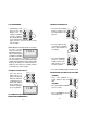
• After approximately 30 seconds the meter
will display 10.00, prompting the user to
place the 10.00 FTU standard solution in
the cuvet holder.
• Place the 10.00 FTU
standard in the holder press CAL, SIP and
CL will start blinking
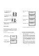
• After approximately
30 seconds the meter
will display 500, asking the user to place
the 500 FTU buffer
solution in the cuvet
holder.
NOTE: At this point the
user can save the two point calibration
setup by pressing ALT & CAL buttons,
leaving the calibration mode.
To perform a three point
calibration, place the 500
FTU standard solution in the
cuvet holder.
• Press CAL, SIP and
CL will start blinking
10.00
cl
sip
cl
500
cl
sip
cl
err1
18
• After approximately
30 seconds the LCD
will display "----".
Now the instrument
is calibrated and
ready for use.
NOTE: If "ERR1" is displayed, the calibra-
tion data is maintained.
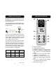
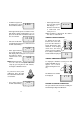
VIEWING CALIBRATION DATE
To display the last cali-
bration time and date,
press the GLP button to
toggle through the date
and time. If the display
shows "FS", the instru-
ment has factory calibra-
tion settings loaded and
no date will be displayed.
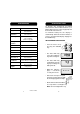
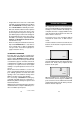
VIEWING FIRMWARE VERSION
To display the firmware version press and
hold the ON/OFF key for
approx. ten seconds
(when turning the meter
on).
The firmware version will
be displayed
LOGGING
MICROPROCESSOR
TURBIDITY METER
LOGGING
MICROPROCESSOR
TURBIDITY
METER
HI 93703-11
VIEW
STO
CLR
GLP
CAL
DATE
READ
ALT
OFF
ON
FS
ENSURE ACCURATE CALIBRATION
The procedure below should be carefully fol-
lowed during testing and calibration:
LOGGING
MICROPROCESSOR
TURBIDITY METER
LOGGING
MICROPROCESSOR
TURBIDITY
METER
HI 93703-11
VIEW
STO
CLR
GLP
CAL
DATE
READ
ALT
OFF
ON
V1.0