Instruction Manual HI 933300 HI 933301 Portable Microprocessor Printing and Logging Multi-Range Conductivity Meters These Instruments are in Compliance with the CE Directives http://www.hannainst.
Dear Customer, Thank you for choosing a Hanna Instruments Product. Please read this instruction manual carefully before using the instrument. This manual will provide you with all the necessary information for the correct use of the instrument, as well as a precise idea of its versatility in a wide range of applications. These instruments are in compliance with directives EN 50081-1 and 50082-1. TABLE OF CONTENTS Preliminary Examination ............................. 1 General Description ...................
PRELIMINARY EXAMINATION Remove the instrument from the packing material and examine it to make sure that no damage has occurred during shipping. If there is any damage, notify your Dealer. Each printing/logging conductivity meter is supplied complete with: • HI 76302W Conductivity Probe with 1 m (3.3') screened cable • AA size Alkaline Batteries (4 pcs) • Paper roll (10 pcs) • Rugged carrying case Note: Save all packing materials until you are sure that the instrument functions correctly.
The stored data can be retrieved at a later time for printing or can be transferred to a computer through an optional HI9200 infrared transmitter. The HI 933300 will transfer the data in seconds through the infrared lights with no need for a cable between the transmitter and the meter. The internal software allocates memory space to store up to 8,000 readings. The meters provide automatic temperature compensation with the supplied HI76302W 4-ring probe with integrated temperature sensor.
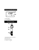
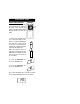
LCD DISPLAY FUNCTIONAL DESCRIPTION 1 mS 2 INTV LOG LO BAT 1. Primary Display 2. Secondary Display FUNCTIONAL DESCRIPTION HI 76302W CONDUCTIVITY PROBE 1 2 3 4 1. 2. 3. 4. Watertight Shielded Screened Cable Air-Release Holes PVC Protective Sleeve 4 Stainless Steel Rings.
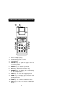
FUNCTIONAL DESCRIPTION HI 933300 1 2 3 mS LOG 4 5 6 7 MICROPROCESSOR LOGGING CONDUCTIVITY METER 5. 6. 7. 8. 9. 10. 11. 10 9 PRINT PAPER ALT CAL CFM TIME LOG 8 RANGE 1. 2. 3. 4.
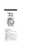
FUNCTIONAL DESCRIPTION HI 933301 1 2 3 mS LOG 4 5 6 7 1. 2. 3. 4. 5. 6. 7. 8. 9. 10. 11.
SPECIFICATIONS HI 933300 & HI933301 Measurement Range µS/cm µS/cm mS/cm mS/cm °C Resolution 0.0 150 1.50 15.0 0.0 to to to to to 150.0 1500 15.00 199.9 60.0 0.1 µS/cm, 1 µS/cm 0.01 mS/cm, 0.1 mS/cm, 0.1°C Accuracy (@20°C/68°F) ±1% full scale; ±0.5°C excluding probe error Typical EMC Deviation ±1% F.S ±0.5°C Calibration Automatic 1, 2, 3, 4 or 5 points at 0, 84, 1413, 12880, 80000 µS/cm Temperature Compensation Automatic from 0 to 60 °C (32 to 140°F) with variable ß from 0.0 to 3.
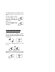
OPERATIONAL GUIDE INITIAL PREPARATION Each meter is supplied complete with batteries. Remove the back cover, unwrap the batteries and install them while paying attention to their polarity. - 1.5V + 1.5V - - 1.5V + + 1.5V - + SCREW POTS To prepare the instrument for use, connect the probe to the meter securely by aligning the pins with the socket located on the top of the instrument, pushing the plug in and tightening the threaded ring.
To maximize battery life, the display is automatically switched off after 5 minutes of nonuse. The meter continues to monitor (if in the logging or recording mode) conductivity and ON/OFF temperature even when the display is off. To revive the display, press either the ON/OFF or the RANGE key. RANGE SETTING DATE/TIME /PRINTING INTERVAL (for HI933300 only) Press the ALT and the TIME keys simultaneously. The display will show the date setting. At the bottom of the display the year will start blinking.
Select the month by using the UP or DOWN arrow key. or CAL CFM Press the TIME key. The day will start blinking. DATE TIME Use the UP or DOWN arrow key to select the correct day. or CAL CFM Press the ALT and the TIME keys simultaneously. The display will now show the time and the printing interval will start blinking. ALT CAL TIME INTV RANGE TIME The interval can be selected from 1, 2, 5, 10, 15, 30, 60, 120 or 180 minutes by using the UP and DOWN arrow keys.
Once the desired interval is selected press the TIME key once to set it. The hour will start blinking. TIME TIME INTV To select the hour press the UP or DOWN arrow key (24 hour clock). or CAL CFM Press the TIME key once. The minutes will start blinking. TIME TIME INTV Use the UP or DOWN arrow key to select the minute. or CAL CFM Press the ALT and the TIME keys to leave this mode.
VIEWING TIME / DATE / CONDUCTIVITY / TEMPERATURE (for HI 933300 only) To view the time press the TIME key. This also displays the selected interval time. TIME INTV TIME To view the date, press the UP arrow key when the LCD is displaying the time. DATE CAL To view the conductivity and temperature press the RANGE key. Conductivity will be displayed on the primary display and temperature on the secondary (without decimal point). mS RANGE To view the temperature press the RANGE key again.
SETTING DATE/TIME/PRINTING INTERVAL (for HI933301 only) Press the ALT and the RANGE keys twice simultaneously. The display will show the date setting. At the bottom of the display the year will start blinking. DATE ALT RANGE Use the UP or DOWN arrow key to select the year. or CAL CFM When the correct year is selected, press the TIME key once. The month will start blinking. DATE RANGE Select the month by using the UP or DOWN arrow key. or CAL CFM Press the RANGE key.
Use the UP or DOWN arrow key to select the correct day. or CAL CFM Press the ALT and the RANGE keys simultaneously. The display will now show the time and the printing interval will start blinking. ALT TIME INTV RANGE The interval can be selected from 1, 2, 5, 10, 15, 30, 60, 120 or 180 minutes by using the UP and DOWN arrow keys. or CAL CFM Once the desired interval is selected press the RANGE key once to set it. The hour will start blinking.
Press the RANGE key once. The minutes will start blinking. TIME INTV RANGE Use the UP or DOWN arrow key to select the minute. or CAL CFM Press the ALT and the RANGE keys simultaneously to leave this mode. ALT RANGE The meter's time, date and interval are now set and stored in memory even when the display is switched off. VIEWING TIME / DATE / CONDUCTIVITY / TEMPERATURE (for HI 933301 only) To view the time press the ALT and RANGE keys simultaneously. This also displays the selected interval time.
To view the date, press the UP arrow key when the LCD is displaying the time. DATE CAL To view the conductivity and temperature press the RANGE key. Conductivity will be displayed on the primary display and temperature on the secondary (without decimal point). mS RANGE To view the temperature press the RANGE key again. The temperature will be displayed on the primary display with a decimal point.
Use the UP and the DOWN arrow key to change the setting. or CAL CFM TAKING CONDUCTIVITY MEASUREMENTS Make sure that the meter has been calibrated before taking any measurements (see page 18). To take a measurement, place the probe into the solution with the holes completely submerged. Tap and stir the probe to remove all air bubbles that may be trapped inside the PVC sleeve.
Once the reading stabilizes mS the measurement is complete. If further measurements are desired, rinse the probe with tap water and test the next sample. Note: The probe body and sleeve are made of PVC and are very susceptible to damage due to temperatures exceeding 50°C (122°F). If the probe is exposed to high temperature, the bond between the rings and the probe body may become impaired and the probe will not function properly, in which case it has to be replaced.
CONDUCTIVITY CALIBRATION It is recommended that HI 933300 and HI 933301 are calibrated frequently for greatest accuracy, especially when used often or in samples with widely differing conductivity values. For best results choose conductivity solutions that are closest in value to the sample to be measured. For accurate calibraRINSE CALIBRATION tion, use two beakers for each solution: the first one for rinsing the probe, the second one for calibration. In this way cross contamination is minimized.
PROCEDURE FOR OFFSET CALIBRATION (at 0.0 µS/cm) • To perform the Offset calibration, dry the conductivity probe and leave it in air. • Press the ALT and the CAL keys simultaneously. The primary LCD display will blink "0.0 µS" for about 10 seconds. µS ALT CAL • When "0.0 µS" stops blinking, the calibration can be confirmed. Press the CFM key to confirm the offset value. µS CFM • If the input reading is out of the offset range, an error message will show on the secondary display "E0".
PROCEDURE FOR SINGLE POINT CALIBRATION WITH BUFFER SOLUTION HI933300 and HI933301 have auto-buffer recognition: you can simply place the probe into the type of buffer solution that you need to calibrate and perform the single point calibration very quickly as described below. Choose one of the following calibration solutions: 84.0 µS/cm (cal. solution HI 7033/HI8033) 1413 µS/cm (cal. solution HI 7031/HI8031) 12.88 mS/cm (cal. solution HI 7030/HI8030) 80.0 mS/cm (cal.
• When the buffer value stops blinking, indicating that the probe has stabilized, press the CFM key to confirm the value. mS CFM • Press the CAL key to exit the calibration mode now. CAL PROCEDURE FOR A COMPLETE CALIBRATION WITH 5 BUFFERS HI933300 and HI933301 have 5 memorized calibration values: 0.0 µS/cm (probe in air) 84.0 µS/cm (cal. solution HI 7033/HI8033) 1413 µS/cm (cal. solution HI 7031/HI8031) 12.88 mS/cm (cal. solution HI 7030/HI8030) 80.0 mS/cm (cal.
• When "0.0 µS" stops blinking, the calibration can be confirmed. Press the CFM key to confirm the offset value. µS CFM • If the input reading is out of the offset range, "E0" as error message will appear on the secondary display . Press the CAL key to re-calibrate the value. CAL HI 7 03 3 • If everything is satisfacµS tory the LCD will blink "84.0 µS", expecting the next calibration solution (HI7033 or HI8033). • Fill a beaker with HI7033 or HI 8033 conductivity calibration solution.
• If the value is out of the slope range, an "E1" error message will appear on the secondary display. Press the CAL key to re-calibrate the value. CAL HI 703 1 • If everything is satisfactory the LCD will blink µS "1413 µS", expecting the next calibration solution (HI 7031 or HI 8031). • Wait for 1 minute, then immerse the probe into the HI7031/HI 8031 cali8 cm (3¼") bration solution. The level of solution must be higher than the holes on the PVC sleeve.
0 703 HI • If everything is satisfacmS tory the LCD will blink "12.88 mS", expecting the next calibration solution (HI7030 or HI 8030). • Wait for 1 minute, then immerse the probe into the HI7030/HI8030 cali8 cm bration solution. The level (3¼") of solution must be higher than the holes on the PVC sleeve. Tap the probe repeatedly on the bottom of the beaker and stir it to ensure that no air bubbles are trapped inside the sleeve. • When the "12.
than the holes on the PVC sleeve. Tap the probe repeatedly on the bottom of the beaker and stir it to ensure that no air bubbles are trapped inside the sleeve. • When the "80.0 mS" stops blinking, indicating that the measurement has stabilized, press the CFM key again to confirm the fifth calibration point. mS CFM • If the value is out of the slope range, an "E4" error message will appear on the secondary display. Press the CAL key to re-calibrate the value.
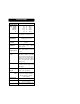
CONDUCTIVITY VERSUS TEMPERATURE CHART As shown in the chart below, temperature has an effect on conductivity. °C °F HI7030 HI7031 HI7033 HI7034 HI7035 HI7039 HI8030 HI8031 HI8033 HI8034 HI8035 HI8039 (µS/cm) (µS/cm) (µS/cm) (µS/cm) (µS/cm) (µS/cm) 0 32 7150 776 64 48300 65400 2760 5 41 8220 896 65 53500 74100 3180 10 50 9330 1020 67 59600 83200 3615 15 59 10480 1147 68 65400 92500 4063 16 60.8 10720 1173 70 67200 94400 4155 17 62.
TEMPERATURE CALIBRATION (for Technical Personnel only) INITIAL PREPARATION Prepare a container of ice and water and another container with hot water (at a temperature of at least 50°C/122°F). Place insulation material around the containers to minimize temperature changes. Use a ChecktempC or a calibrated thermometer with a resolution of 0.1° as reference thermometer. °C °C 50 °C (122 °F) 0 °C (32 °F) Note: After performing the following calibration, conductivity must be recalibrated.
into the PVC sleeve with the holes towards the top (the end nearest to the cable) of the probe. °C • Place the probe into the container with ice and water (0.0°C/32°F). 0 °C (32 °F) • Press the CAL key. The secondary (lower) display will blink "0" for about 30 seconds. CAL • When "0" stops blinking, the calibration can be confirmed. Press the CFM key to confirm the first value. CFM • If the value is out of the offset range, an error message will show on the secondary display "E1".
• If everything is satisfactory the LCD will blink "50" expecting the second buffer (50°C/122°F). Note: if a single point calibration is required, press the CAL key to leave the calibration mode now. CAL °C • Place the probe into the second container with hot water (50°C/122°F). 50 °C (122 °F) • When "50" stops blinking, press the CFM key again to confirm the second calibration point. CFM • If the value is out of the slope range, an error message will show on the secondary display "E2".
PRINTING/RECORDING WITH HI933301 To print the measured values press the PRINT key. The printout provides the following information: PRINT a - Running log number b - Date (DD-MM-YY) c - Time (HH-MM) d - Conductivity value in µS/cm or mS/cm e - Temperature in degrees Centigrade. a b 29-03-96 --01-*15.01 147.6 µS c 25.1 °C d e RECORDING MODE (PROGRAMMED PRINTOUTS ) Set the appropriate printing interval (see Operational Guide section on page 12).
Each printout provides the following information: a - Running log number. b - Running sample number in that particular log. c - Date (DD-MM-YY) d - Printing interval indicator in minutes e - Time (HH-MM) f - Conductivity value in µS/cm or mS/cm g - Temperature in degrees Centigrade. a b 29-03-96 <> --01-0015 c 0001M *16.59 d 5137 µS e 25.9 °C f g When the meter is in the recording mode "LOG" is displayed on the bottom left corner of the LCD.
• It is possible to insert a new paper roll during the recording mode (see page 46). Once in the logging mode, the interval cannot be changed. Exit the logging mode (pressing the ALT and the RECORD keys simultaneously) before setting the new interval (see page 12). If the PRINT key is pressed while still in recording mode, an adPRINT ditional printout is produced without affecting the running sample number.
PRINTING/LOGGING WITH HI933300 To print the measured values shown on display, press the PRINT key once. PRINT This function can be activated in normal operation mode as well as during logging and scanning data on display (see below). When in measurement mode, the printout provides the following information: a - Running log number b - Date (DD-MM-YY) c - Time (HH-MM) d - Conductivity value in µS/cm or mS/cm e - Temperature in degrees Centigrade. a 29-03-96 b --01-*18.01 1455 µS 25.
bol will appear on the bottom left corner of the LCD. ALT CAL CFM TIME LOG LOG RANGE 29-03-96 0001M <> --01-0001 *18.05 1455 µS 25.9 °C Press the ALT and the PAPER keys at the same time and the "LOG" symbol on the display will start to blink. PRINT PAPER LOG ALT CAL After approximately 5 minutes the display will switch off but the logging function remains active. To reactivate the display press any key except the ALT key. Notes: • Once in the logging mode, the interval cannot be changed.
• If the PRINT key is pressed while in logging mode, a printout is produced without affecting the running sample number. PRINT SAMPLE NUMBER During logging it is possible to know the running sample number. Reactivate the display if the meter is in standby mode by pressing any key (except the ALT key). Press the LOG key twice and the display will show the number of values that have been taken until now in the current log.
29-03-96 <> --01-0001 0001M *16.07 5897 µS 25.9 °C During logging with printing, the display shows TIME the time, interval and the LOG INTV “LOG” symbol. To display the conductivity value, press the RANGE key. µS RANGE If no key is pressed, the display goes blank after about 5 minutes. To reactivate the display press any key except the ALT key. Each printout provides the following information: a - Running log number.
It is always possible to switch from the logging with printing function to the logging function only. Press the ALT and the PAPER keys at the same time and the "LOG" symbol will start to blink, indicating that the data are only stored in memory and not printed. PRINT PAPER LOG ALT CAL Notes: • • • • It is recommended to use the voltage adapter (HI 710005 or HI 710006) during logging with printing mode, especially when many printouts are going to be performed.
TO STOP LOGGING Press the ALT and the LOG keys simultaneously, this will generate a log exit status print out. ALT RANGE CAL CFM TIME LOG 29-03-96 0001M <> --01-0009 *16.15 5814 µS 25.6 °C Log # 29-03-96 0001M <> --01-- Total Sample # 0009 *16.15 Date Printing Interval Ending Time TO SCAN STORED DATA ON DISPLAY Press the LOG key. The display will show the log number and the page number of the next log.
Press the ALT and the RANGE keys simultaneously. This now shows the date in which logging has commenced. ALT DATE RANGE Press the UP arrow key and the time will be displayed. TIME CAL Press the UP arrow key and the temperature will be displayed. °C CAL Press the UP arrow key and the conductivity value will be displayed. mS CAL Continue pressing the UP arrow key to display one by one all the memorized data of the same log in the above sequence, i.e. time, temperature, conductivity value.
To exit from the recall mode press the LOG key. CFM Note: this mode will not alter data in memory. TO PRINT STORED DATA LOG Having selected a log number by using ALT and CFM keys, as detailed in the chapter "TO SCAN STORED DATA ON DISPLAY" you can print all or part of that log section by using the ALT and PRINT keys. The printer will then start to print the logged section beginning with the selected sample number without altering the content of the memory.
"PAPER" simultaneously and the printer will immediately stop. PRINT ALT PAPER CAL Note: Before proceeding with printing, make sure there is enough paper for the data to be printed. When the paper is finished the meter will not advise the operator and the printouts could be lost. If this happens, stop the printer by pressing ALT and PAPER key simultaneously. Data will be kept in memory.
DATA TRANSFER TO PC HI 933300 contains infrared emitting circuitry. Set the meter to TIME mode and simply place your datalogger on a HI 9200 Infrared Transmitter (ensuring that the two infrared LEDs are placed on top of each other) and the contents of the memory can then be downloaded to your PC through the HI 9200's RS 232 port. TIME During the data transfer the instrument displays the message "r 232".
HI 92000 allows you to use the powerful means of the most widely used spread sheet programs available (e.g.Excel©, Lotus 1-2-3©). Simply open your file downloaded by HI 92000 from your spread sheet program and then it is possible to make any elaboration available with your software (e.g. graphics, statistic analysis). User friendly, HI 92000 offers a variety of features and has on line help to support you throughout any situation. To install HI 92000 you need a 3.
FAULT FUNCTIONS HI 933300 and HI 933301 are factory programmed to automatically diagnose a fault. This is displayed with error codes on the LCD. Error codes: PEr 0, PEr 1, PEr 2 = Short circuit on the system, the meter should be returned for repair (see Warranty section). PEr 3 = Printer mechanism fault - repair needed (see Warranty section). PEr 4 = Printer clutch jammed - reset the printer (see page 47). PEr 9 = Printer jammed - reset the printer (see page 47).
MEMORY ORGANIZATION (HI933300) Capacity: 8000 data samples which are divided into 16 pages. Each time a new logging period starts, it automatically starts from a new page. If the logging function is still on, and the available page is 0 the meter will overwrite the first lot of data in the existing memory. During logging the meter automatically returns to the oldest page in memory and if it contains data, it will overwrite.
PRINTER MAINTENANCE TO CHANGE THE INK CARTRIDGE When printouts become faint, it might be necessary to change the ink cartridge. Contact your Hanna authorized center. TO INSERT THE PAPER ROLL The HI 933300 and HI 933301 use plain paper rolls 38 mm width. To insert a new roll is very easy. Open the paper cover pulling it gently. Take the carton cylinder away. Insert the paper edge in the printer slot and feed the printer by pressing the PAPER key.
Allow about 5 cm (2") to exit from the printer and replace the paper cover. TO RESET PRINTER Investigate the cause of the printer jam (e.g. the paper caught under the cover that has prevented printer from advancing paper feed). Press the PAPER key to reset the printer.
PROBE MAINTENANCE Rinse the probe with tap water after every series of measurements. If a more thorough cleaning is required, remove the PVC sleeve and clean the probe with a cloth or a nonabrasive detergent. When reinserting the sleeve onto the probe, be sure that the sleeve is in the right direction with the four holes towards the cable end. After cleaning the probe, re-calibrate the instrument. The probe body is in PVC and for this reason must never come into close contact with sources of heat.
BATTERY REPLACEMENT When the batteries are run down "LOBAT" is displayed on the Liquid Crystal Display to warn the user. Battery replacement must only take place in a non hazardous area using 1.5V alkaline AA type batteries. LO BAT - 1.5V + 1.5V - - 1.5V + + 1.5V - + SCREW POTS In order to replace run down batteries, simply remove the two screws on the rear cover of the instrument and replace the four 1.5V AA batteries with new ones, paying attention to the correct polarity.
ACCESSORIES CONDUCTIVITY CALIBRATION SOLUTIONS HI 7030L 12880 µS/cm (µmho/cm), 460 mL HI 7030M 12880 µS/cm (µmho/cm), 230 mL HI 7031L 1413 µS/cm (µmho/cm), 460 mL HI 7031M 1413 µS/cm (µmho/cm), 230 mL HI 7033L 84 µS/cm (µmho/cm), 460 mL HI 7033M 84 µS/cm (µmho/cm), 230 mL HI 7034L 80000 µS/cm (µmho/cm), 460 mL HI 7034M 80000 µS/cm (µmho/cm), 230 mL HI 7035L 111800 µS/cm (µmho/cm), 460 mL HI 7035M 111800 µS/cm (µmho/cm), 230 mL HI 7039L 5000 µS/cm (µmho/cm), 460 mL HI 7039M 5000 µS/cm
POWER UNITS HI710005 Voltage adapter from 115 VAC to 12 VDC HI710006 Voltage adapter from 230 VAC to 12 VDC OTHER ACCESSORIES CHECKTEMPC Electronic thermometer (range -50.0 to 150.0°C) HI 710031 Hard carrying case HI 710034 Plain Paper Spare Rolls (10 pcs) HI 710035 Spare Ink Cartridge (1pc) HI 721308 1.5V AA alkaline battery (10 pcs) HI 76302W 4-ring probe with temperature sensor with 1 meter (3.3') cable HI 9200 Infrared Transmitter (for HI 933300 only) HI 92000/16 Windows® 3.
WARRANTY All Hanna Instruments meters are warranted for two years against defects in workmanship and materials when used for their intended purpose and maintained according to the instructions. The probes are warranted for a period of six months. Damages due to accident, misuse, tampering or lack of prescribed maintenance are not covered. This warranty is limited to repair or replacement free of charge. If service is required, contact the dealer from whom you purchased the instrument.
CE DECLARATION OF CONFORMITY DECLARATION OF CONFORMITY We Hanna Instruments Srl V.le delle industrie 12 35010 Ronchi di Villafranca (PD) ITALY herewith certify that the conductivity meters HI 933300 HI 933301 have been tested and found to be in compliance with the following regulations: IEC 801-2 IEC 801-3 IEC 801-4 EN 55022 Electrostatic Discharge RF Radiated Fast Transient Radiated, Class B Date of Issue: 15-03-1996 D.Volpato - Engineering Manager On behalf of Hanna Instruments S.r.l.
h t t p : / / w w w . h a n n a i n s t .